
Installation / Operation Instruction Manual


page 3
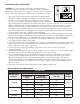
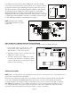
UNIT SIZE CHART
MAXIMUM BTU/
HR INPUT*
MAX. EQUIVALENT FEET OF VENT PIPE
VENTING WITH VENT
PIPE SIZE
MODEL
NUMBER
AT MAXIMUM
INPUT
AT 60% OF
MAXIMUM INPUT
290,000
16 44 4"
SWGII-551 100 5"
95 100 6"
416,000
28 78 5"
SWGII-668 100 6"
100 100 7"
505,000 65 65 10" SWG-8
INSTALLATION OF SWG POWER VENTER
*Do not exceed maximum BTU/HR input rating.
INSTALLATION SAFETY INSTRUCTIONS
CAUTION: This device must be installed by a qualified installer in
accordance with the manufacturer's installation instructions. Appliances
should have a minimum of 75% combustion efficiency or have a maximum
measured flue gas temperature of 550ºF at the inlet of the power venter.
The power venting system must be installed by a qualified installer. 1.
"Qualified Installer" shall mean an individual who has been properly
trained or is a licensed installer. The installer must write or imprint
his name, phone number, and date of installation on the installation
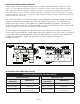
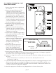
tag. The tag should be attached to the system control kit box or power venter unit. Also, the included
adhesive "Warning!" label should be attached to the Control Kit box, as shown in Figure 1, and the
installers name be written on it. Recording burner and venting system initial operational information
is strongly recommended as a guide for service or burner tune-up. Enter this on the back page of this
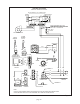
manual. The appropriate wiring diagram for the type of controls on the water heater must be affixed to
the water heater jacket upon completion of the installation.
Safety inspection of a venting system should be performed before and after installing a power venting 2.
system on an existing or new appliance. Procedures to follow are those recommended by the National
Fuel Gas Code, ANSI Z223.1, or refer to General Installation Inspection section of this manual.
Plan the vent system layout before installation to avoid the possibility of accidental contact with 3.
concealed wiring or plumbing inside walls.
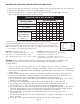
Single wall vent pipe (refer to Diagram B) may be used to join an appliance to the venting system, but if 4.
proper clearances cannot be maintained from combustible materials, Class B Vent Pipe should be used.
Refer to national or local codes for guidelines.
Disconnect power supply before making wiring connections to prevent electrical shock and 5.
equipment damage.
This equipment is designed to overcome minor negative pressure conditions. To ensure extreme negative 6.
pressure does not exist, follow General Installation Inspection of this manual.
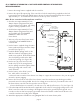
The commercial water heaters for the SWGII-5 and 6 power venters have draft hoods, and each kit 7.
includes a GSK-3 spillage switch which must be installed on the bottom of the draft hood to detect
spillage of flue products due to inadequate venting draft or vent system blockage. In the event of
excessive flue spillage from the draft hood, the spillage switch will interrupt power to the gas valve to
stop the burners. Refer to the installation instructions for the spillage switch in the Installation section of
these instructions.
The power venter must be installed downstream of the appliance draft hood.8.
Figure 1