
Installation / Operation Instruction Manual
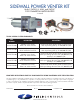


page 7
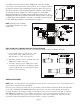
Figure 8
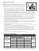
WIRING INSTRUCTIONS
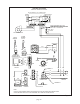
NOTE: Refer to the appropriate wiring diagrams contained in these instructions for the corresponding control
system for the water heater being installed.
Wire the power venter motor and controls in accordance with the National Electrical Code and applicable
local codes. UNIT MUST BE GROUNDED. Check ground circuit to make certain that the unit has been
properly grounded. The wiring should be protected by an over-current circuit device rated at 15 amperes.
CAUTION MUST be taken to ensure that the wiring does not come in contact with any heat source. All
line voltage and safety control circuits, between the power venter and the appliance, MUST be wired in
accordance with the National Electrical Code for Class 1 wiring or equivalent.
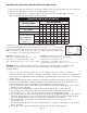
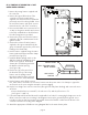
CLASS B AND CLASS L DOUBLE WALL VENT PIPE INSTALLATION
(Follow vent pipe manufacturer's listed or recommended clearances from combustible material.)
Using a hand crimper or a like device, crimp 1.
the inner pipe of the SWG power venter
approximately 1" long. (See Figure 8)
Attach the vent pipe over the crimped end of the 2.
SWG power venter inner pipe.
Secure the vent pipe to the SWG power venter 3.
inner pipe with at least three (3) #8 sheet metal
screws. Pre-drilling the holes through both pipes
will allow easier fastening.
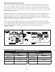
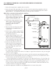
To install an outer pipe extension to the SWG power venter, the end pipe
cover on the power venter must be removed. Then, cut a 1" square notch into
the vent pipe extension before attaching to the power venter. (See Figure 6)
This allows clearance for the adjustment damper. Install the required length
of outer pipe extension lengths as needed for clearance to combustible
materials. Terminate the outer pipe extension with the end pipe cover. (See
Diagram B) The table shows minimum allowable clearances when using single
or double pipe systems. When the outer pipe is extended over the inner pipe
use the double pipe guidelines when determining clearances.
NOTE: Vent pipe joints should be
secured with at least three (3) sheet
metal screws.
Figure 6
Figure 7