
Installation / Operation Instruction Manual


page 8
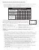
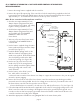
Figure 10
DRAFT HOOD
SELF-TAPPING SHEET
METAL SCREW
GSK-3 SPILL
SWITCH
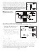
CK-41 CONTROL KIT WIRING FOR 24 VOLT
WATER HEATER CONTROLS
Remove the wiring harness supplied with 1.
the control kit.
Remove the upper left knockout of the 2.
control box. Push the snap bushing
supplied over the knockout hole created to
prevent the wires from being chafed. Insert
the end of the harness with quick connect
terminals into the side of the control box.
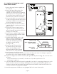
Disconnect the black wire connected to TH 3.
or 24V on the ignition module and connect
to the fully insulated tab on the black wire
from the wiring harness provided.
Connect the yellow wire from the harness 4.
supplied to the TH or 24V terminal on the
ignition module.
Connect the red wire from the harness 5.
supplied to the upper terminal block (the
group of terminals opposite the yellow wire
leading to the thermostat).
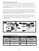
Run the harness supplied along the water 6.
heater jacket and support with the clamps
provided. (See Figure 9)
Install the GSK-3 spillage switch on the 7.
draft hood with the self-tapping sheet
metal screw supplied. The thermal
element disc should hang just below
the draft hood relief opening.
(See Figure 10)
Run the two (2) yellow wires from 8.
the break in the top of the wiring
harness into the spillage switch
through the plastic bushing opening
and connect to the switch terminals.
Run the harness to the CK-41 junction 9.
box, which will be mounted in a convenient location near the power venter. Use clamps to support the
wire harness to the joists at regular intervals to prevent sagging.
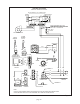
Run the low voltage wires into the control box (through hole with plastic bushing) and connect the wires 10.
as follows:
Connect the black wire to terminal T1, the red wire to T2, and the yellow wire to T3.
(See Figures 13 and 14)
Follow the National Electrical Code and/or applicable local codes for running high voltage wires to the 11.
CK-41 control box and wire according to the diagram. Unit must be grounded. Check ground circuit
to make sure the unit has been properly grounded. Connect the flexible conduit from the blower to the
control box and wire according to the diagram.
Attach the appropriate self-adhesive wiring diagram label to the water heater jacket.12.
Figure 9