
Spec Sheet

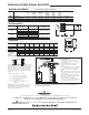

Gas Power Vent Models
Meets California Energy Commission Requirements.
Kit
Number
F
Vent
Outside
Height
E
Vent
Outside
Width
D
Distance
Extending
from Wall
C
Max Wall
Thickness
B
Clearance
Diameter
A
Flue Size
Part Number in. mm.
239-81764-00 (24 Volts)
9
1
⁄
4
9
1
⁄
4
9
1
⁄
4
1
239-81766-00 (24 Volts)
239-82148-00 (24 Volts)
Amp Draw
1.3
2.1
4.4
5
6
8
127
152
203
in. mm.
7
8
10
178
203
254
in. mm.
12
12
13
305
305
330
in. mm.
235
235
235
10
3
⁄
4
10
3
⁄
4
11
7
⁄
8
in. mm.
273
273
302
12
1
⁄
4
12
1
⁄
4
14
1
⁄
4
in. mm.
311
311
362
2
3
Commercial Gas Power Vent Kits
General
Dimensions and specifications subject to change without notice in accordance with our policy of
continuous product improvement.
Unit Sizing Chart
Maximum
BTU/Hr. Input
Maximum Equivalent
of Vent Pipe
ft. m.
290,000
16
51
95
4.8
15.5
28.9
399,999
505,000
239-81764-00 (24 Volts)
239-81766-00 (24 Volts)
239-82148-00 (24 Volts)
28
68
100
8.5
20.7
30
65 19.8
Venting with
Vent Pipe Size
in. mm. Part Number
4
5
6
102
127
152
5
6
7
127
152
178
10 254
Equivalents
Vent Pipe Fittings†
3"
(76mm.)
ft. m.
19
5
3
Tee
90° Elbow
45° Elbow
5.8
1.5
.9
Sudden Reducer
or Increaser for
Three Ratios
(d/D)
8
5
2.4
1.5
2
d/D
.6
4"
(102mm.)
ft. m.
25
7
4
7.6
2
1.2
11
7
3.4
2
3.9
5"
(127mm.)
ft. m.
31
9
4
9.5
2.7
1.2
14
8
4
2.4
3.9
6"
(152mm.)
ft. m.
38
11
5
11.6
3.4
1.5
17
10
7
3
4 1.2
7"
(178mm.)
ft. m.
44
12
8
13
3.7
2.4
19
12
5.8
3.7
4 1.2
8"
(203mm.)
ft. m.
50
14
7
15
4.3
2
22
13
6.7
4
5 1.5
9"
(229mm.)
ft. m.
56
15
8
17
4.6
2.4
25
15
7.6
4.6
6 1.8
10"
(254mm.)
ft. m.
63
18
9
25
5
3
28
17
9
5
6 1.8
3
⁄
4
1
⁄
2
1
⁄
4
†Not included with kit.
*Reducer or increaser ratio 4 ft. (d/D) small diameter divided
by the larger diameter. Example 4 ft. to 8 ft. reducer; the
reducer ratio is d/D = 4/8 = 1/2. To estimate the equivalent
length figure. Example 4" (102mm) to 8" (203mm) reducer;
the reducer ratio is 1/2 and the smaller pipe diameter is 4"
(102mm). So, from the chart, the equivalent feet would be
7 ft. (2 meters).
Example: System Pipe Size – 4" (102mm)
Step 1 Two 4 ft. (102mm) 90° Elbows @ 7 ft.
(2 meters) each = 14 ft. (4.3 meters)
Step 2 Ten 2 ft. Lengths of 4" (102mm)
Pipe = 20 ft. (6 meters)
Step 3 Total Equivalent Feet = 14 ft.
(4.3 meters) + 20 ft. (6 meters) = 34 ft.
(10.4 meters)
CAUTION:
Failure to install, maintain and/or operate the
power venting sytem in accordance with manufacturer’s
instructions will result in conditions which may produce
bodily injury and/or property damage.
Dd
Venting Requirements
1. The exit termination shall not be less than
7 ft. (2m) above grade when located adjacent
to public walkways.
2. The vent shall terminate at least 3 ft. (.9m)
above any forced air inlet located within
10 ft. (3m).
3. The vent shall terminate at least 4 ft. (1m) below,
4 ft. (1m) horizontally from, or 1 ft. (.3m) above
any door, window or gravity air inlet into the
building.
4. The vent termination point shall not be installed
closer than 3 ft. (.9m) from an inside corner of an
L-shaped structure.
5. The vent termination should not be mounted
directly above, or within 3 ft. (.9m) horizontally
from an oil tank vent or gas meter.
6. The bottom of the vent terminal shall be
located at least 1 ft. (.3m) above finished grade
or above maximum expected snow level.
AB
DC
E
F
Printed in U.S.A.
2140-B-0313-A
©2013, Bradford White Corporation. All rights reserved.
Ambler, PA
For U.S. and Canada field service, contact your professional installer or local Bradford White sales representative.
Sales 800-523-2931
●
Fax 215-641-1670 / Technical Support 800-334-3393
●
Fax 269-795-1089
●
Warranty 800-531-2111
●
Fax 269-795-1089
International: Telephone 215-641-9400
●
Telefax 215-641-9750 / www.bradfordwhite.com
Sales / Technical Support 866-690-0961 / 905-238-0100
●
Fax 905-238-0105 / www.bradfordwhite.com