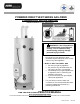
POWERED DIRECT VENT SERIES GAS-FIRED COMMERCIAL WATER HEATER (INDEPENDENT PVC VENTING) WARNING: If the information in these instructions is not followed exactly, a fire or explosion may result causing property damage, personal injury or death. - Do not store or use gasoline or other flammable vapors and liquids in the vicinity of this or any other appliance. - WHAT TO DO IF YOU SMELL GAS Do not try to light any appliance. Do not touch any electrical switch; do not use any phone in your building.
SECTION I: IMPORTANT INFORMATION READ CAREFULLY This gas-fired water heater is design certified by CSA International under the American National Standard, Z21.10.3 and CAN/CGA 4.3-M (as indicated on the rating plate). These standards are available from CSA Standards Association, 5060 Spectrum Way Mississauga, Ontario L4W 5N6 CANADA. This water heater must be installed in accordance with local codes. In the absence of local codes, it must be installed in compliance with the National Fuel Gas Code (ANSI Z223.
DANGER DO NOT store or use gasoline or other flammable, combustible, or corrosive vapors and/or liquids in the vicinity of this or any other appliance. This water heater is equipped with an adjustable thermostat to control water temperature. Hot water temperatures required for automatic dishwasher and laundry use can cause scald burns resulting in serious personal injury and/or death. The temperature at which injury occurs varies with the person’s age and the time of exposure.
WARNING This water heater needs fresh air for safe operation and must be installed so there are provisions for adequate combustion and ventilation air. Insufficient air supply will cause a recirculation of combustion products resulting in contamination that may be hazardous to life. This will result in carboning or sooting of the combustion chamber, burners, and flue tubes and creates a risk of asphyxiation.
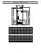
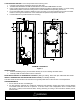
SECTION II: SPECIFICATIONS Figure 1. Dimensional layout Model Description Capacity Input (BTU/hr) (Gal) Nat. LP 100 199,999 199,999 100 150,000 150,000 100 250,000 225,000 80 250,000 225,000 80 199,999 199,999 80 150,000 150,000 A (In.) 72.13 72.13 72.13 63.13 63.13 63.13 Dimensions for Figure 1 B C D (In.) (In.) (In.) 60.31 77.19 56.81 60.31 77.19 56.81 60.31 82.13 56.81 51.31 68.19 47.81 51.31 68.19 47.81 51.31 68.19 47.81 E (In.) 74.13 74.13 74.13 65.13 65.13 65.
SECTION III: GENERAL INFORMATION FEATURES 1. Porcelain enamel lined tank provides corrosion protection with a tough glass lining on the interior of the tank. 2. Magnesium anodes provide an extra measure of protection and extends tank life. 3. Direct Vent design with an induced draft blower. Flue gases are exhausted and combustion air is taken from outside the building through 3” or 4” PVC, CPVC, or ABS pipe.
DISHWASHING MACHINE REQUIREMENTS All dishwashing machines meeting the National Sanitation Foundation requirements are designed to operate with water flow pressures between 15 and 25 pounds per square inch. Flow pressures above 25 pounds per square inch, or below 15 pounds per square inch, will result in improperly sanitized dishes. The National Sanitation Foundation also recommends circulation of 180°F water.
SECTION IV: INSTALLATION INSTRUCTIONS WARNING INSTALLATION OF THIS WATER HEATER REQUIRES ABILITY EQUIVALENT TO THAT OF A LICENSED TRADESMAN IN THE FIELD INVOLVED. PLUMBING, AIR SUPPLY, VENTING, GAS SUPPLY AND ELECTRICAL WORK ARE REQUIRED. DO NOT ATTEMPT TO LIGHT ANY GAS APPLIANCE IF YOU ARE NOT CERTAIN OF THE FOLLOWING: Liquefied petroleum gases/propane gas and natural gas have an odorant added by the gas supplier that aids in detection of the gas.
Minimum Clearances CAUTION The National Fuel Gas Code (ANSI Z233.1- latest edition) or in Canada The Natural Gas or Propane Installation Code CAN/CGA (B149.1, B149.2- latest edition), expressly prohibits the following: a. Installation of a water heater in a bathroom, bedroom, or any occupied room normally kept closed. b. Installation of a water heater in a garage, unless the unit is installed so that the burner and ignition devices are at least eighteen (18) inches (45.
LOCATE WATER HEATER in front of final position before removing crate. 1. LOCATE so that venting connections will be short and direct. 2. THIS WATER HEATER IS SUITABLE FOR INSTALLATION ON COMBUSTIBLE FLOOR. 3. Proper venting practices must be considered when selecting a location for this water heater. For exact venting specifications, please consult the Venting section of these Installation and Operating Instructions. 4. It is recommended that a minimum clearance of four (4) inches (10.
SECTION V: VENTING WARNING The direct vent system must be properly installed. Failure to properly install the direct vent system could result in property damage, personal injury, or death. DO NOT install any damaged venting system components. If damage is evident then please contact the supplier where the water heater was purchased or the manufacturer listed on the rating plate for replacement parts. Use only the vent terminals provided or factory authorized for venting this water heater.
NOTICE For installations in Canada, field supplied vent piping must comply with CAN/CGA B149.1 (latest edition) and be certified to the Standard For Type BH, Class II, 65°C, Gas Venting Systems, ULC S636. Components of this listed system must not be interchanged with other vent systems or unlisted pipe/fittings. All components and specified primers and cements of the certified vent system must be from a single system manufacturer and not intermixed with other system manufacturer’s vent system parts.
Figure 3.
The vent system must terminate so that proper clearances are maintained as cited in local codes or the latest edition of the National Fuel Gas Code, ANSI Z223.1.73.4e and 7.8a, b as follows: 1. Do not terminate near soffit vents or crawl space or other area where condensate or vapor could create a nuisance or hazard or cause property damage. 2.
Direct Vent System Installation (199,999 and 150,000 Btu/hr. input models) WARNING The direct vent system must be properly installed. Failure to properly install the direct vent system could result in property damage, personal injury or death. The water heater requires its own separate venting system. Do not connect the exhaust vent into an existing vent pipe or chimney. CAUTION Do not install any damaged direct vent system components. Contact the manufacturer of the water heater for replacement parts.
CAUTION IMPORTANT - All of the Exhaust Venting connections must be leak checked with a soap solution upon initial start up of the water heater. Any leaks must be repaired before continuing operation of the water heater. Through the Wall Venting: Cut two 3 1/2” (8.9 cm) diameter holes (for 3” (7.6 cm) diameter pipe) or 4 1/2” (11.4 cm) diameter holes (for 4” (10.2 cm) diameter pipe) in the wall with the centerline hole distances at least 6” (15.
Figure 6 Figure 7A Figure 7B 17
Figure 7C Through the Wall Venting With Low Ground Clearance: When venting cannot exit through the wall at a height greater than or equal to 12” (30.5 cm) (and above expected snow level) from the ground, then the installation must be modified as shown below (see Figure 8). Refer to Tables 3 or 4 for maximum venting lengths using 3” (7.6 cm) or 4” (10.2 cm) diameter pipe. Figure 8 TABLE 3 3” (7.
Direct Vent System Installation for Models with Input Ratings Over 200,000 Btu/Hr. Models with input ratings over 200,000 Btu/hr. must use 4” (10.2 cm) diameter pipe. Install the blower adaptor exhaust vent assembly and gasket supplied in the vent kit carton on the exhaust blower outlet flange as described in the previous section. Connect the 4” (10.2 cm) pipe to the 4” (10.2 cm) reducers attached to the combustion air intake pipe and blower exhaust outlet. The supplied 4” (10.
SECTION VI: WATER CONNECTIONS NOTE: BEFORE PROCEEDING WITH THE INSTALLATION, CLOSE THE MAIN WATER SUPPLY VALVE. After shutting off the main water supply, open a faucet to relieve the water line pressure to prevent any water from leaking out of the pipes while making the water connections to the water heater. After the pressure has been relieved, close the faucet. The COLD water inlet and HOT water outlet are identified on the top and front of the water heater.
WARNING Keep clear of combination temperature and pressure relief valve discharge line outlet. The discharge may be hot enough to cause scald injury. The water is under pressure and may splash.
SECTION VII: GAS CONNECTIONS The gas supply lines must meet all requirements of the National Fuel Gas Code (ANSI Z223.1-Latest Edition), or in Canada CAN/CGA B149.1 Natural Gas Installation Code (Latest Edition) or CAN/CGA B149.2 Propane Installation Code (Latest Edition). The minimum permissible gas supply pressure for the purpose of input adjustment is one (1.0) inch (0.25 kPa) water column above the operating manifold pressure. See the rating plate and gas valve for the manifold pressure and gas type.
SECTION IX: ELECTRICAL CONNECTIONS WARNING Turn off or disconnect the electrical power supply to the water heater before servicing. Label all wires prior to disconnection when servicing controls. Wiring errors can cause improper and dangerous operation. Verify proper operation after servicing. All electrical wiring must be installed and grounded in accordance with local codes, or in the absence of local codes, the National Electrical Code, ANSI/NFPA 70 and/or CSA C22.2 Electrical Code.
TYPICAL INSTALLATION Notes: The heat trap shown above is not part of the water heater, only a piping suggestion to reduce the standby heat loss. The drain pan may be purchased from your water heater supplier. WARNING Water heaters are heat-producing appliances. To avoid damage or injury there must be no materials stored against the water heater or direct vent system, and proper care must be taken to avoid unnecessary contact (especially by children) with the water heater and direct vent system.
Lighting And Shutdown Instructions Temperature down CAUTION Do not use this appliance if any part has been under water. Immediately call a qualified service technician to inspect the appliance and to replace any part of the control system including gas controls, which has been under water.
SECTION X: OPERATING INSTRUCTIONS TEMPERATURE ADJUSTMENT APPROXIMATE TIME/TEMPERATURE RELATIONSHIPS IN SCALDS 120°F (49°C) More than 5 minutes 125°F (52°C) 1½ to 2 minutes 130°F (54°C) About 30 seconds 135°F (57°C) About 10 seconds 140°F (60°C) Less than 5 seconds 145°F (63°C) Less than 3 seconds 150°F (66°C) About 1½ seconds 155°F (68°C) About 1 second DANGER Hotter water increases the risk of scald injury. Scalding may occur within five (5) seconds at a temperature setting of 140F (60C).
Water Heater Display and Control Buttons Shown flashing in display only when temp is adjusted Sequence of operation Indicator Reads "Idle” or “Heating" Status Indicator Read "Operational" or "Service Needed" Temperature Up Button °F setpoint idle Status Operational SELECT SET Temperature Setpoint in Degrees F or Degrees C Range 70 - Max °F Range 21 - Max °C Temperature Down Button Set button Select button WARNING If the water heater display does not show “Operational” in the “Status” indicator, the
TO INCREASE SETPOINT TEMPERATURE Step 1: Depress and hold “Temperature Up” button until desired setpoint temperature appears in the display. °F idle Status Operational SELECT SET Step 1 Step 2: “Setpoint” indicator begins flashing in the display after pressing “Temperature Up” button. "Setpoint" flashes °F setpoint idle Status Operational SELECT SET Step 2 Step 3: Press “SET” button for new setting to take effect immediately. “Setpoint” will stop flashing.
To Decrease Setpoint Temperature Step 1: Depress and hold “Temperature Down” button until desired setpoint temperature appears in the display. °F idle Status Operational SELECT SET Step 1 Step 2: “Setpoint” indicator begins flashing in the display after pressing “Temperature Down” button. "Setpoint" flashes °F setpoint idle Status Operational SELECT SET Step 2 Step 3: Press “SET” button for new setting to take effect immediately. The setpoint will stop flashing.
To Change Temperature Format in Display from F to C or ˚C to ˚F: Step 1: Press “SELECT” button until F/C is displayed. °F °F/°C idle Status Operational SELECT Press select SET Step 1 Step 2: Press “SET” button to change temperature format. Symbol F/C will flash. °F °F/°C idle Status Operational SELECT SET °F/°C Flashes Step 2 Step 3a: Press “Temperature Up” button to change temperature format to C.
Step 3b: Press “Temperature Down” button to change temperature format to F. Changes to "°F" °F/°C Flashes °F °F/°C idle Status Operational SELECT SET Step 3b Step 4: Press “SET” button to confirm ˚F or ˚C format. F/C will stop flashing. Setpoint display will appear in the format selected (˚F or ˚C) in 10 seconds.
An automatic gas shut-off device (ECO) is incorporated in the sensor and control board which will shut off all gas supply to the burner and pilot if the water heater temperature exceeds 200°F (93°C). Should the ECO function (open), the water temperature should be reduced to approximately 120°F (49°C) and follow Lighting Instructions to place the water heater in operation. The water heater must have the problem corrected by a qualified service person before putting the water heater back in operation.
SECTION X: MAINTENANCE Burner Flame Check At the time of installation and at periodic intervals (about every 3 months), a visual check of the pilot and burner flames should be made to determine if they are burning properly. No adjustment to the air shutter should be required for this heater. The burner flames should be blue with yellow tips. A blue-orange flame is characteristic of operation on liquefied petroleum (LP) gas.
A qualified service technician should perform the following maintenance at the minimum periodic intervals suggested below. In some installations, the maintenance interval may be more frequent depending on the amount of use and the operating conditions of the water heater. Regular inspection and maintenance of the water heater will help to insure safe and reliable operation. 1.
To reinstall the burner rack, reverse the above procedure. Alternate method for removing the burner rack, when there is at least 20” (50.8 cm) clearance on the left front side: a) Shut off the gas and electrical supply to the water heater. b) Disconnect both pilot tube fittings at the combustion box bulkhead fitting. c) Disconnect wires to gas valve. Open control box and disconnect pilot spark and flame sense wires. d) Disconnect the gas pipe union either above or below the gas valve.
13. The induced draft blower motor used in this model series has sealed bearings and does not have provisions for oiling the bearings. 14. The vent system must be inspected at least once a year to ensure against leakage of exhaust products. CAUTION FOR YOUR SAFETY, DO NOT ATTEMPT REPAIR OF COMBINATION GAS CONTROL, BURNERS OR GAS PIPING. REFER REPAIRS TO A QUALIFIED SERVICE TECHNICIAN.
SECTION XI: DIAGNOSTIC AND TROUBLESHOOTING GUIDE DIAGNOSTIC GUIDE FOR HONEYWELL INTEGRATED CONTROL SYSTEM SEQUENCE OF OPERATION FOR PDV AND INDUCED DRAFT MODELS 1. When the tank temperature drops below the temperature setpoint on the display, the control sends power to the induced draft blower to start the ignition sequence. 2. When blower reaches the full operating speed, the pressure switch closes, completing the 24 volt circuit to the safety circuit of the control.
ACCESSING SERVICE MODE ON THE WATER HEATER DISPLAY (FOR SERVICE PERSONNEL ONLY) The display has a “service mode” for changing the maximum setpoint and accessing information in aiding servicing of the water heater. This procedure is for service and installation personnel only. To enter the Service Mode, follow the steps illustrated below: WARNING The following procedure is for service and installation personnel only.
The following is the sequence of modes available in “Service Mode” by pressing the “Select” button: Error Code Number (Display/Reset). This is only shown if there is an operating error in the “User Mode”. Error Code Shown in Water Heater Display Status Service Needed SELECT Lockout RESET 1. Max Setpoint (Display/Change) Max Setpoint value Water Heater Display °F Max Setpoint idle Status Operational SELECT SET 2a.
2b. Water Temperature - Upper Sensor (Displays if there is an upper sensor – some models) °F idle Status Operational Upper Sensor SELECT SET 2c. Water Temperature - Lower Sensor (Displays if there are two sensors) °F idle Status Operational Lower Sensor SELECT SET 3.
4. Setpoint (Display/Change) °F setpoint idle Status Operational SELECT SET 5. ˚F/˚C (Display/Change) °F °F/C° idle Status Operational SELECT SET 6.
7. Software Version (Display only) Soft idle Status Operational SELECT SET 8. Error Code History (Displays if there are present error codes or up to 10 previous error codes). Water Heater Display will show -- if there are no error codes.
Step 2: Press “Set” button to enter setting mode. “Max Setpoint” will flash to indicate setting mode. "Max Setpoint" Flashes °F Max Setpoint idle Status Operational SELECT SET Step 3: Press the “UP” or “DOWN” buttons to change the maximum setpoint value. This will limit the maximum setpoint the user can select. Note: The maximum setpoint is approximately 180˚F.
Step 5: 30 Seconds after the last button press, the Water Heater Display will go back to “User Mode”. It will read “Max Setpoint” without showing a temperature value if the temperature setpoint is at the maximum setting. The Water Heater Display can be set back to the “User Mode” immediately by pressing both the “Temperature Up” and “Select” buttons together for 3 seconds.
Step 2: For water heaters using two temperature sensors, pressing the “Select” button again displays the Upper Sensor temperature reading. “Upper Sensor” will be displayed in the lower right side of the status window of the water heater display. °F idle Status Operational Upper Sensor SELECT SET Step 3: For water heaters using two temperature sensors, pressing the “Select” button again displays the Lower Sensor temperature reading.
To Display and Change Temperature Setpoint: Step 1: In “Service Mode” press the “Select” button until “Setpoint” is shown in the water heater display. °F setpoint idle Status Operational SELECT SET Step 2: Press the “Set” button to enter the setting mode. “Setpoint” will flash in the water heater display.
Step 4: To lower the temperature setpoint, press the “Temperature Down” button until the desired temperature is shown on the water heater display. "Setpoint" Flashes °F setpoint idle Status Operational SELECT SET Step 5: When the desired setpoint is reached on the water heater display, press the “Set” button to confirm the new setpoint. “Setpoint” stops flashing in the water heater display.
Step 2: Press “Set” button to change temperature format. “˚F/˚C” symbol will flash in the water heater display. "°F/°C" Flashes °F °F/C° idle Status Operational SELECT SET Step 3a: Press “Temperature Up” button to change temperature format to ˚C. Changes to "°C" "°F/°C" Flashes °C °F/C° idle Status Operational SELECT SET Step 3b: Press “Temperature Down” button to change temperature format to ˚F.
Step 4: Press “Set” button to confirm ˚F or ˚C format. ˚F/˚C will stop flashing. "°F/°C" Symbol Stops Flashing °F °F/C° idle Status Operational SELECT SET Step 5: Pressing “Select” button will return display to setpoint in format selected (˚F or ˚C) immediately.
How to reset the control from Lockout Conditions: WARNING The following procedure is for service and installation personnel only. Resetting lockout conditions without correcting the malfunction can result in a hazardous condition. If an error code is displayed (except for #4, low flame sense current), the water heater will be in a “lockout condition” with the water heater display showing the error code number and “Service Needed” in the status section of the display window.
Error Codes and Error History Display: If there is an operating problem with the water heater, an error code number will appear on the water heater display with “Service Needed” to the right of the “Status” indicator. The error code label is located below the water heater display and the following section in this Installation and Operating Instruction Manual explains the error codes with corrective actions to repair the water heater.
Step 2: Press the “Temperature Down” button to select the error code index, starting with the most recent error code “10”. Error Code Index idle Status Operational SELECT SET Step 3: Press the “Select” button to view the error code for “code 10”. If there is a number displayed, note what the number is. The label next to the water heater display will identify the code number.
Step 4: Press the “Temperature Down” button to change to the previous code index, code #9. Error Code Index idle Status Operational SELECT SET Step 5: Press the “Select” button for code index #9 to view if there are any code numbers.
Step 6: Continue pressing the “Temperature Down” button to change to the next error code index and press “Select” to view the error code number, if any, for that index number. Continue on to index #1, the oldest error code index. The water heater display will store up to 10 error codes with the oldest code starting in code index #1 with the most recent code in code index #10. Step 7: 10 seconds after the last button press, the Water Heater Display will revert back to the current error code display.
Error Code Definition of Code 23 Flame Detected Before Ignition 24 31 32 57 58 59 Flame Detected After Heating Cycle Completes Upper Sensor Readings Faulty Lower Sensor Readings Faulty Flame Rod Shorted to Ground AC Line Frequency Error – Signal Too Noisy or Frequency Incorrect Line Voltage Too Low or High 61 DC Output Voltage Unstable 62 Maximum Number of Retries Detected 63 Maximum Number of Ignition Recycles Detected 64 Electronics Failure 65 High Water Temperature (Over 200˚F) Cause of
Procedure for Checking Thermostat Sensors Set the thermostat above water temperature (See temperature adjustment section) and observe system through one (1) complete cycle. Make sure system operates as desired. To check the upper sensor or lower sensor assembly, compare the resistance of the sensor terminals (blue leads for upper sensor, yellow and black lead for lower sensor) as measured by an ohmmeter to the water temperature as measured by an accurate thermometer.
SECTION XII: PARTS LIST PART NAME AND DESCRIPTION 1. Induced Draft Blower Assembly 2. Diptube 3. Pressure Switch 4. T&P Valve 5. Flue Baffle 6. Cleanout Access (Jacket) Cover 7. Drain Valve 8a. Cleanout Cover 8b. Cleanout Cover O-Ring (under cover – not shown) 9. Main Burner Tubes 10. Pilot Assembly 11. Pilot Supply Tube (Control Side) 12. Pilot Supply Tube (Burner Side) 13. Main Burner Manifold 14. Gas Valve 15. Main Burner Orifice 16. Transformer 17. Ignition Module 18.
VENT KIT COMPONENTS AND OPTIONAL CONDENSATE TEE 150,00 AND 199,999 BTU/HR. MODELS: 3” VENT KIT MODELS OVER 200,000 BTU/HR.
SECTION XIII: INSTALLATION FOR POTABLE WATER AND SPACE HEATING THE FOLLOWING INSTRUCTIONS ARE FOR INSTALLATION OF: GAS WATER HEATERS SUITABLE FOR WATER (POTABLE) HEATING AND SPACE HEATING 1. All piping components connected to this water heater for space-heating applications must be suitable for use with potable water. In Massachusetts, space heating piping must not exceed 50 feet. 2. Toxic chemicals, such as those used for boiler treatment, must not be introduced into potable water used for space heating.
SECTION XIV: NOTES 60