Installation and Operation instructions INDOOR MODEL RTG 199 HE Warning: If the information in this manual is not followed exactly, a fire or explosion may result causing property damage, personal injury or death. Do not store or use gasoline or other flammable vapors and liquids in the vicinity of this or any other appliance. Installation and service must be performed by a trained and certified installer, service agency or the gas supplier.
Table of contents Table of contents 1 Key to symbols and safety instructions . . . . . . . . . . . . . . . . . . . 3 1.1 Key to symbols . . . . . . . . . . . . . . . . . . . . . . . . . . . . . . . . . 3 1.2 Safety instructions . . . . . . . . . . . . . . . . . . . . . . . . . . . . . . 3 2 FCC rules . . . . . . . . . . . . . . . . . . . . . . . . . . . . . . . . . . . . . . . . . . . . . 6 3 Appliance details . . . . . . . . . . . . . . . . . . . . . . . . . . . . . . . . . . . . . . 6 3.1 Features .
Key to symbols and safety instructions 1 Key to symbols and safety instructions 1.1 Key to symbols Warnings Warnings in this document are identified by a warning triangle printed against a grey background. Keywords at the start of a warning indicate the type and seriousness of the ensuing risk if measures to prevent the risk are not taken. The following keywords are defined and can be used in this document: • NOTICE indicates that damage to property may occur.
Key to symbols and safety instructions Risk of scalding at the hot water draw-off point ▶ When the water heater is in operation, temperatures in excess of 122 °F (50 °C) can occur. To limit the temperature at the tap, install a thermostatic DHW mixing valve. ▶ Water heated for washing the laundry, dishes and for other cleaning purposes can cause scalding and permanent injuries. ▶ Children, elderly, and handicapped persons are more likely to be permanently injured by hot water.
Key to symbols and safety instructions For your safety ▶ Do not store or use gasoline or other flammable, combustible or corrosive vapors and liquids in the vicinity of this or any other appliance. DANGER: Fatal accidents! Carbon monoxide poisoning. ▶ Carefully plan where you install the heater. Correct combustion air supply and flue pipe installation are very important. If a gas appliance is not installed correctly, fatal accidents can result such as carbon monoxide poisoning or fire.
FCC rules WARNING: Personal Injury from toxic chemicals. ▶ A water heater which will be used to supply potable water shall not be connected to any heating system or component(s) previously used with a nonpotable water heating appliance. 2 FCC rules FCC: This device complies with Part 15 of the FCC rules.
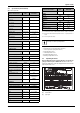
Appliance details 3.2 Specifications (Technical data) Technical characteristics LP Gas Approved in US/Canada Technical characteristics Capacity Maximum flow rate at a 45 °F (25 °C) rise Maximum flow rate at a 55 °F (30.6 °C) rise Maximum flow rate at a 75 °F (41.7 °C) rise Maximum flow rate at a 90 °F (50 °C) rise Maximum output Maximum input Units RTG 199 H GPM (l/min) 8.3 (31.4) GPM (l/min) 6.8 (25.7) Units RTG 199 H V AC 120 Hz 60 mA 40 A 2.
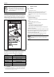
Appliance details 3.3.1 The box includes • Tankless water heater • Bracket for wall hanging the heater • Exhaust vent adaptor (with 4 screws and gasket provided) • Combustion air inlet adaptor (with 3 screws and gasket provided) • Installation manual • Energy Guide label ▶ Lift front cover panel upward and remove. The RTG 199 H is not approved or designed for: • Manufactured (mobile) homes, boats or any mobile installation. (Modular homes are acceptable for installation). • Use above 8000 ft A.S.L.
Appliance details • 2. Carefully plan where you install the heater. Correct combustion air supply and vent pipe installation are very important. If not installed correctly, fatal accidents can occur, such as carbon monoxide poisoning or fire. • 3. When the unit is installed indoors and ROOM SEALED (twin pipe) it is permitted to be located in bathrooms, bedrooms and occupied rooms that are normally kept closed. See chapter 4.3 (page 10).
Installation instructions 4 Installation instructions 4.1 Specialized tools The following specialized tools may be required for installation: • Manometer • Multi-meter • Combustion Gas Analyzer 4.2 Introduction Please follow these instructions. Failure to follow instructions may result in: ▶ Damage or injury. ▶ Improper operation. ▶ Loss of warranty. DANGER: ▶ The water heater must be installed by a qualified installer in accordance with these instructions.
Installation instructions 4.3.
Installation instructions 4.3.2 Vent specifications Establish vent clearances that comply with the vent manufacturer's specifications and all applicable national/local codes. Venting specifications Diam.
Installation instructions For this example, the maximum allowable exhaust pipe length is 13 feet. Combustion air For this example, the maximum allowable combustion air pipe length is 48 feet. Calculation example for 2" PVC venting: Exhaust System used Number of 90° elbows needed: Concentric 2 Number of 45° elbows needed: 1 Table 14 System used Number of 90° elbows needed: Number of 45° elbows needed: Twin pipe 1 0 Table 20 Calculation of example Max.
Installation instructions Required direct vent terminal clearances (twin pipe / concentric penetration) for PVC, CPVC, ABS, and PP. Fig. 10 A Clearance above grade, veranda, porch, deck or balcony Canadian installations1) 12 in. B Clearance to window or door that may be opened 36 in. 12 in.
Installation instructions Required other than direct vent terminal clearances (single pipe penetration) for PVC, CPVC and ABS systems. Fig. 11 A Clearance above grade, veranda, porch, deck or balcony Canadian installations1) 12 in. B Clearance to window or door that may be opened 36 in.
Installation instructions 4.3.3 Vent configuration examples for PP, PVC, CPVC, or ABS systems Below are approved examples of vertical and horizontal venting installations. WARNING: ▶ Single pipe penetration should be used in nonfreezing climates only and steps must be taken to ensure that adequate combustion air is available to the water heater at all times! Fig. 14 Horizontal venting system (concentric vent) Fig.
Installation instructions Fig. 17 Exhaust connection Fig. 16 Horizontal venting system (single pipe penetration) [1] [2] [3] [LA] ▶ Attach the combustion air inlet accessory to the top of the unit fig. 18 (position 2) using the 3 screws and gasket provided, and install 3" air intake pipe over the accessory.
Installation instructions Use materials approved by the authority having jurisdiction. In the absence of other authority, PVC, and CPVC pipe must comply with ASTM D1785, F441 orD2665. Cement and primer must comply with ASTM D2564 or F493. For Canada, use CSA or ULC certified PVC or CPVC pipe, fittings and cement, see table 5. PP pipe must be certified under ULC S636. Appliance condensate drain installation The appliance comes equipped with an internal condensate drain and siphon.
Installation instructions Installation For this solution to be effective, the internal flapper must be 100% closed when the water heater is not running. Refer to Figures 23 and24 for preferred installation positions in the vent system. Installation considerations: • Install damper per the supplied manufacturer‘s instructions. • The damper is only to be used in the exhaust vent piping. • Ensure directional arrow on damper label faces in the same direction as exhaust flow.
Installation instructions 4.3.7 Common venting of 2 to 4 units 2 to 4 unit cascades can be common vented using the optional PP common venting system. The water heaters can be installed in a back to back configuration as shown in fig. 26, or side by side as shown in fig. 27. The systems are custom configurable for vent lengths from 40” (1m) up to 100’ (30m) and either a vertical or horizontal termination (see fig. 25).
Installation instructions 4.3.8 Fan speed adjustment necessary adjustments to fan speed values may result in improper operation of the appliance. NOTICE: IMPORTANT INFORMATION! ▶ Natural gas heaters with installation altitudes below 2,000 ft above sea level disregard this section. Installation adjustment: After installing the tankless water heater, the fan speed values for minimum power (P2) and maximum power (P1) may need adjustment due to variations in altitude and vent pipe length.
Installation instructions Altitude (above sea level) 0 - 2000 ft (0 - 610 m) Natural Gas Minimum power fan speed (P2) No modification required Liquid propane Minimum power fan speed (P2) No modification required Natural Gas Maximum power fan speed (P1) No modification required Liquid propane Maximum power fan speed (P1) No modification required 3.5 - 39 ft 11* 14* 52* 52* 40 - 86 ft 11* 14* 53* 53* 3.5 - 59 ft 10* 13* 52* 52* 60 - 126 ft 11* 14* 53* 53* 3.
Installation instructions ▶ Press and hold ( 5 sec.) “Program” button P until the display flashes, then the selected value is memorized.
Installation instructions Although it is permissible to draw combustion air from the inside, it is not the manufacturer’s recommended installation method. Always install a 3 inch 90° elbow on the top of the combustion air inlet adaptor to prevent foreign objects from falling into the unit. If a single pipe installation is utilized, follow guidelines below for providing adequate combustion air for the water heater as well as any other appliances that may consume air in the same space.
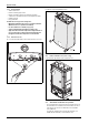
Installation instructions Fig. 30 Distance between support boards [1] Studs 16" (406mm) on center Fig. 32 Mounting the heater CAUTION: Personal injury and property damage. ▶ Appliance must be installed vertically. 4.8 Mounting installation When installing this appliance the unit must be additionally secured at the bottom of the water heater as shown in fig. 33. Use the included screws to secure the brackets at the bottom of the water heater to the wall.
Installation instructions 4.9 Gas piping & connections Before connecting the gas supply, check the rating plate on the right side of the heater to be sure that the heater is rated for the same gas to which it will be connected. Example rating plate can be found in fig. 2, page 7. In the United States: The installation must conform with local codes or, in the absence of local codes, the National Fuel Gas Code ANSI Z223.1/ NFPA 54.
Installation instructions 4.9.1 Gas Line Sizing Tables for NATURAL GAS For your convenience see below for an excerpt from gas line sizing tables for a single NG appliance. For details see the current NFPA 54. Specified pipe lengths are for one RTG 199 H which has a maximum input rating of 199,000 BTUs. The gas supply system must be sized for the combined total maximum BTU/hr load requirements of all gas appliances running simultaneously.
Installation instructions 4.9.2 Gas Line Sizing Tables for LP GAS For your convenience see below for an excerpt from gas line sizing tables for a single LP appliance. Their intended use of is for pipe sizing between the the 2nd stage (low pressure) regulator and the appliance. For details see the current NFPA 54 or NFPA 58. Specified pipe lengths are for one RTG 199 H which has a maximum input of 199,000.
Installation instructions 4.10 Water connections NOTICE: ▶ This heater is not approved for preheated water applications exceeding 140°F (60°C). NOTICE: ▶ In applications where inlet water temperature can exceed 140°F (60°C), a 3-way valve or mixing valve must be installed before the appliance to prevent water exceeding 140°F (60°C) from entering the appliance. ▶ When facing the heater, the ¾ ” cold connection is on the bottom right and the hot connection is on the bottom left.
Installation instructions ▶ Open the four clips and remove the combustion cover, see fig. 5, page 8. ▶ Remove the clip and disconnect the drain tube, see fig. 39. Fig. 39 Disconnect drain tube Fig. 37 Plumbing Connections (with shutoff valves) and Pressure Relief Valve 4.12 ▶ Fill the condensate trap by pouring approx.14 oz. (400ml) of water into the top of the drain tube. To avoid damage to the appliance use a funnel in this operation, see fig. 40, page 30.
Installation instructions ▶ Check water level in the condensate trap. 4.14 Space heating applications CAUTION: ▶ If the set point temperature is above 120°F, precautions should be taken to protect users of potable water from scalding. CAUTION: ▶ Propylene glycol may be used for freeze prevention ONLY on the space heating side of the heat exchanger. Do not use ethylene glycol (automotive antifreeze). Fig. 42 Water level in condensate trap ▶ After filling reassemble all parts in reverse order. 4.
Installation instructions Fig. 44 Pressure drop curve Fig.
Electrical connections 4.15 Measuring gas pressure Confirm gas pressure upon installation. Connecting manometer ▶ Shut off gas supply at installer supplied shutoff valve for this water heater. ▶ Remove front cover and locate inlet gas pressure test port (see Fig.47). ▶ Loosen screw inside left test point fitting (do not remove) and connect manometer tube to test point. Static Pressure Test ▶ Turn gas supply back on. ▶ Record static gas pressure reading in table 40.
Operation instructions ▶ Remove the six screws from the back cover of the control unit, see fig. 50, pos. 2. ▶ Check the fuses in the printed circuit board, see fig. 50, pos. 3. Fig. 48 Connecting power supply cord [1] Power cord length: 3ft. Note: The outlet the appliance is plugged into should be clear from possible water damage. 5.2 Position of the fuses in control unit To check fuses, proceed as follows: ▶ Remove the front cover, see fig. 4, page 8.
Operation instructions Fig. 53 Temperature indicator Fig. 59 Activation water flow (see chapter 12) 6.2 For your safety read before operating your water heater DANGER: Explosion hazard! ▶ If you do not follow these instructions exactly, a fire or explosion may result causing property damage, personal injury or loss of life. Fig. 54 Error indicator Fig. 55 Locked condition indicator (only with remote control) Fig. 56 Flame indicator A.
Operation instructions ▶ Press buttons + or in order to reach desired temperature. 6720608920-12.1AL Fig. 61 Setting the water temperature The desired temperature of the hot water can be adjusted on the front control panel of the heater. The water heater has an electronically controlled gas valve that modulates the burner input in response to both varying hot water flow rates and/or changes in any incoming and outgoing water temperatures.
Maintenance and service NOTICE: ▶ Inspect and clean the complete water heating system once a year. ▶ Carry out a maintenance as necessary. Immediately repair all faults to avoid damage to the system. Annual maintenance table 6720608920-15.1AL Fig. 65 Reset button If the problem persists, contact your installer. 6.7 Program button 1. Inspect venting system Every year X 2. Inspect combustion chamber X 3. Inspect burner X 4. Inspect condensate trap X 5.
Maintenance and service 7.2 Winterizing for seasonal use The water heater must not be installed in a location where it may be exposed to freezing temperatures. If the heater must be left in a space which is likely to experience freezing temperatures, all water must be drained from the heater. If precautions are not taken, resulting damage will not be covered under the warranty.
Maintenance and service ▶ Dismantle all parts for inspection and cleaning. ▶ Insert CO2 analyzer probe into the measuring port. The tip of the probe should be in the center of the flue pipe (approx 1.5" inserted). Avoid air gaps between probe and measuring port as they can alter readings. Fig. 71 Measuring port ▶ Press the ON/OFF button to turn ON the heater. ▶ Immediately following, press and hold simultaneously buttons + or and P for 3 seconds, until display reads P2. Fig.
Maintenance and service Max. CO level CO2 range (%) (measured) Nat. Gas max. input P1 7.8 % - 8.4 % < 250 ppm min. input P2 1.5 % - 1.8 % < 60 ppm max. input P1 9.5 % - 10.1 % < 250 ppm min. input P2 1.9 % - 2.2 % < 60 ppm LP Gas * Values above are for climate controlled conditions. Inputs such as gas pressure, heating value of the gas, humidity and temperature of combustion air all impact CO and CO2 values.
Maintenance and service Program P0 Description By-pass calibration Factory Default - MIN - MAX - Comment Contact manufacturer for details. P1 Maximum Power NG: 51, LP: 52 21 NG: 53, LP: 53 P2 Minimum Power NG: 10, LP: 13 NG: 8, LP: 11 20 see chapter 4.15, page 33 note: reducing P1 values below maximum will reduce maximum power of the appliance. see chapter 4.3.8, page 21 P3 _0 _0 6 Not available E 0d 10f see chapter 7.
Troubleshooting Example: Calculation of number of working hours, Diagnostic menu 10F 10th most recent error 1P* Appliance type - Cd (Condensing) Appliance type - nC (Non condensing) 2P* Appliance power - 175 / 199 (kBTU/hr) 3P* Temperature range - H (100-140°F) Temperature range - C (100-184°F) Working hours Number in H0 60 60 + Number in H1 5 (X 100) = 500 + Number in H2 0 (X 10 000) = (H0 + H1 + H2) = Total of hours 0 560 H0 Numbers of hours - mode 0 Table 47 H1 Numbers of hours -
Troubleshooting 7. Check for plumbing crossover. A crossover in the hot and cold plumbing pipes creates back pressure on the water flowing through the heater. Therefore, a higher flow rate than normal is needed to force the heater to activate. To check for a plumbing crossover, shut off the cold water supply to the water heater. Then open all of the hot water taps served by the heater. Wait 10 minutes and check for water flow at each tap. There should be no water flowing.
Problem solving 8.7 Noisy burner/heater during operation 1. Sealed combustion leak. Make sure combustion cover is securely fastened. Ensure the exhaust vent adaptor is properly sealed with supplied gasket. Leaky seals create improper combustion resulting in noise. 2. Improper venting. Venting that is unsealed, the wrong material, too big in diameter or too long in run will result in unstable burner flames and noise. Ensure venting is in accordance with specifications in chapter4.3, page 10. 3.
Problem solving Display C6 Cause Primary fan rotation too low in operation. C7 (Flashing) CA E1 E2 E3 E4 E9 Solution 1. Disconnect power supply cord and check wire connection on back side of fan and the connectors on the control board. 2. Check supply voltage. It must be 120VAC and properly grounded. 3. Check venting specifications are met. Long vent lengths, venting with more than three elbows, blocked vent or combination venting may cause this failure. 4.
Problem solving Display EA Cause No flame ionization detected with water flow. EC Ionization failure during operation. F1 Parameter in memory not found F2 Internal Operations error F3 Internal memory parameter error F4 Internal memory error F5 Analog test fail F6 Gas type parameter error E7 Appliance parameter not defined F0 Burner Control routine state error E5 Burner Control error E6 Burner Control routine check sum error F8 Fan stopping error Solution 1.
Problem solving Display F9 Cause Gas Control error Solution 1. Check Gas Valve cable harness (connection to gas valve and to ECU) 2. Check Gas Valve (Replace if necessary) 3. Replace ECU (Electronic Control Unit) F7 Ionization error at standby. FA Gas leakage error, gas valve circuit not closing properly. 1. Loose connection to the flame ionization rod.
Electrical diagram 10 Electrical diagram Fig.
Sensor resistance charts 11 Sensor resistance charts Fig. 76 Outlet / Inlet and HE immersion sensor characteristics Fig.
Functional scheme 12 Functional scheme Fig.
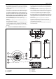
Interior components diagram 13 Interior components diagram 13.1 Interior components Fig.
Protecting the environment 14 Protecting the environment Packing The packing box may be fully recycled as confirmed by the recycling symbol . Components Many parts in the heater can be fully recycled in the end of the product life. Contact your city authorities for information about the disposal of recyclable products. Saving water resources: ▶ Make sure you close all the taps after any use. Avoid leaving the taps dripping. Repair any leaking tap.
LIMITED TANKLESS HEATER WARRANTY 15 LIMITED TANKLESS HEATER WARRANTY BRADFORD WHITE CORPORATION LIMITED TANKLESS HEATER WARRANTY WHAT DOES THIS LIMITED WARRANTY COVER? This limited warranty covers both the heat exchanger and component parts for leakage or other malfunction caused by defects in materials and/or workmanship.
LIMITED TANKLESS HEATER WARRANTY LIMITED TANKLESS HEATER WARRANTY (CONTINUED) WHAT WILL WE DO TO CORRECT PROBLEMS? 1. If a defect occurs within the heat exchanger warranty period, we will: Provide a replacement heater of our manufacture, (or at our option) repair any unit, which develops a leak in the heat exchanger within the warranty period. To obtain a replacement, you must forward both the rating plate from the defective unit to us and a copy of the original sales receipt.
Installer Checklist to be completed by installer upon installation 16 Installer Checklist to be completed by installer upon installation Serial Number (8 digit serial number is located on rating plate on right side panel) ___ ___ ___ ___ ___ ___ ___ ___ Gas Pressure Reading 1) Static Operating Water Pressure Building Water Pressure Range if on Well system Installing Company Installer name Address Phone Table 50 1) See Chapter 4.