
Installation / Operation Instruction Manual
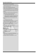
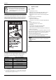
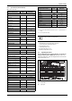
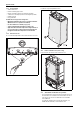
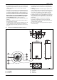
Table Of Contents
- Table of contents
- 1 Key to symbols and safety instructions
- 1.1 Key to symbols
- 1.2 Safety instructions
- 2 FCC rules
- 3 Appliance details
- 4 Installation instructions
- 4.1 Specialized tools
- 4.2 Introduction
- 4.3 Venting
- 4.3.1 Vent options
- 4.3.2 Vent specifications
- Venting specifications
- Condensate drain requirements
- Minimum combustion air and exhaust pipe length
- Maximum combustion air and exhaust pipe length
- Use of elbows
- Calculation example for 3" PVC, CPVC, or ABS venting:
- Calculation example for 4" PP, PVC, CPVC, or ABS venting:
- Calculation example for 2" PVC venting:
- Required direct vent terminal clearances (twin pipe / concentric penetration) for PVC, CPVC, ABS, and PP.
- Required other than direct vent terminal clearances (single pipe penetration) for PVC, CPVC and ABS systems.
- 4.3.3 Vent configuration examples for PP, PVC, CPVC, or ABS systems
- 4.3.4 Vent connections for PP, PVC, CPVC, and ABS systems
- 4.3.5 Connecting the condensate water drain
- 4.3.6 Freeze prevention for PVC, CPVC, and ABS systems
- 4.3.7 Common venting of 2 to 4 units
- 4.3.8 Fan speed adjustment
- 4.4 Combustion air requirements
- 4.5 Proper location for installing your heater
- 4.6 Heater placement and clearances
- 4.7 Hanging appliance on the wall
- 4.8 Mounting installation
- 4.9 Gas piping & connections
- 4.10 Water connections
- 4.11 Water quality
- 4.12 Filling the condensate trap
- 4.13 Domestic hot water recirculation
- 4.14 Space heating applications
- 4.15 Measuring gas pressure
- 5 Electrical connections
- 6 Operation instructions
- 7 Maintenance and service
- 8 Troubleshooting
- 9 Problem solving
- 10 Electrical diagram
- 11 Sensor resistance charts
- 12 Functional scheme
- 13 Interior components diagram
- 14 Protecting the environment
- 15 LIMITED TANKLESS HEATER WARRANTY
- 16 Installer Checklist to be completed by installer upon installation

Installation instructions
RTG 199 HE – 6 720 811 617 (2016/01)
10
Fig. 7 Side view
4 Installation instructions
4.1 Specialized tools
The following specialized tools may be required for installation:
• Manometer
• Multi-meter
• Combustion Gas Analyzer
4.2 Introduction
Please follow these instructions. Failure to follow instructions may
result in:
▶ Damage or injury.
▶ Improper operation.
▶Loss of warranty.
4.3 Venting
For servicing access, a 2ft clearance is recommended to
the front cover.
RTG 199 H
TOP (A) 12”
FRONT (B) 1”
BACK 0”
SIDES 1”
FLOOR (C) 12”
Table 4 Recommended minimum clearances
DANGER:
▶ The water heater must be installed by a qualified
installer in accordance with these instructions. If
improperly installed, a hazardous condition such as
explosion or carbon monoxide poisoning could
result. Manufacturer is not responsible for
improperly installed appliances.
Common installation practice is to first determine the
venting/combustion air point of termination, then
design the piping layout back to the heater.
NOTICE:
▶ Do not reduce the exhaust or combustion air vent
pipe sizes.
▶ Do not common vent with any other vented appliance
or stove.
▶ Do not use Type-B vent as the actual exhaust vent
system for the appliance.
DANGER: Flue gas poisoning!
▶ Failure to vent the exhaust gases to the outside (see
table 5 for proper material) may result in dangerous
flue gases filling the structure in which it is installed.
NOTICE:
▶ In areas where outside temperatures routinely come
close to freezing, sealed combustion operation is
required. Concentric termination or separate
terminations for combustion and vent, must be
installed on the same wall or roof surface; however,
never facing the direction of prevailing winds. Failure
to do so may result in heat exchanger freezing and
bursting. This failure is not covered under the
manufacturer's warranty.
WARNING: Appliance malfunction!
▶ Protect the exhaust and inlet from leaves and debris
by installing a screen on the end of the termination.
¼ " mesh minimum opening recommended on
screen.