
Installation / Operation Instruction Manual
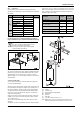
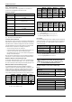
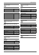
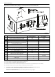
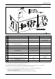
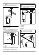
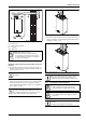
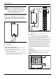
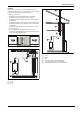
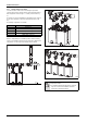
Table Of Contents
- Table of contents
- 1 Key to symbols and safety instructions
- 1.1 Key to symbols
- 1.2 Safety instructions
- 2 FCC rules
- 3 Appliance details
- 4 Installation instructions
- 4.1 Specialized tools
- 4.2 Introduction
- 4.3 Venting
- 4.3.1 Vent options
- 4.3.2 Vent specifications
- Venting specifications
- Condensate drain requirements
- Minimum combustion air and exhaust pipe length
- Maximum combustion air and exhaust pipe length
- Use of elbows
- Calculation example for 3" PVC, CPVC, or ABS venting:
- Calculation example for 4" PP, PVC, CPVC, or ABS venting:
- Calculation example for 2" PVC venting:
- Required direct vent terminal clearances (twin pipe / concentric penetration) for PVC, CPVC, ABS, and PP.
- Required other than direct vent terminal clearances (single pipe penetration) for PVC, CPVC and ABS systems.
- 4.3.3 Vent configuration examples for PP, PVC, CPVC, or ABS systems
- 4.3.4 Vent connections for PP, PVC, CPVC, and ABS systems
- 4.3.5 Connecting the condensate water drain
- 4.3.6 Freeze prevention for PVC, CPVC, and ABS systems
- 4.3.7 Common venting of 2 to 4 units
- 4.3.8 Fan speed adjustment
- 4.4 Combustion air requirements
- 4.5 Proper location for installing your heater
- 4.6 Heater placement and clearances
- 4.7 Hanging appliance on the wall
- 4.8 Mounting installation
- 4.9 Gas piping & connections
- 4.10 Water connections
- 4.11 Water quality
- 4.12 Filling the condensate trap
- 4.13 Domestic hot water recirculation
- 4.14 Space heating applications
- 4.15 Measuring gas pressure
- 5 Electrical connections
- 6 Operation instructions
- 7 Maintenance and service
- 8 Troubleshooting
- 9 Problem solving
- 10 Electrical diagram
- 11 Sensor resistance charts
- 12 Functional scheme
- 13 Interior components diagram
- 14 Protecting the environment
- 15 LIMITED TANKLESS HEATER WARRANTY
- 16 Installer Checklist to be completed by installer upon installation

Installation instructions
RTG 199 HE – 6 720 811 617 (2016/01)
11
4.3.1 Vent options
The water heater is approved with the following venting options:
All combustion air and vent pipe materials and fittings must comply with
the following:
For specific questions concerning vent material, specifications,
usage or installation, please contact the vent manufacturer directly.
Fig. 8 PP Concentric up and out system
The concentric up and out vent system simplifies installations where the
water heater is mounted on an outside wall that can be direct vented
through that wall. This vent system only consists of the concentric
appliance adapter, one 90° elbow, and the termination, and can not be
extended further.
Concentric up and out kit
The concentric up and out system must be installed according to the
respective Installation Manual.
All vent connections must be glued, except for the PP vent systems, and
the exhaust adapter (chapter 4.3.4) which is screwed into place on
the top of the appliance. Slide the vent pipe into the exhaust adapter.
The exhaust pipe must be properly supported and must be pitched a
minimum of a ¼ inch per foot back to the appliance. This allows the
condensate to drain properly.
An optional concentric vent/air intake termination can be used for the
installation of a vertical or horizontal venting system when using PVC,
CPVC, or ABS (see fig. 9).
The concentric vent/air intake body can be ordered from your local
wholesaler.
The appliance can also be installed with separate air intake and exhaust
piping (see fig. 12, fig. 19 and fig. 20, page 18) in PP, PVC, CPVC, and
ABS. Generic PP twin pipe can be used if certified to ULC-S636 and only
with 90° elbow or T terminals. Maximum vent lengths and equivalent
lengths per tables 8 and 9 apply.
Fig. 9 Concentric vent kit example
[1] Exhaust
[2] Combustion air
[3] Roof boot/flashing (field supplied)
[4] Exhaust pipe
[5] Drain tee
[6] Intake pipe
[7] Concentric vent kit (239-44069-01)
[LA] Maintain 12 in. (18 in. for Canada) minimum clearance above
highest anticipated snow level maximum of 24 in. above roof
Item Material United States Canada
Vent
or
air
pipe
and
fitting
PP concentric single ULC-S636
certified only
PP common vent
PP twin pipe
PVC schedule 40 ANSI/ASTM D1785
PVC-DWV ANSI/ASTM D2665
CPVC schedule 40 ANSI/ASTM F441
ABS-DWV schedule ANSI/ASTM D2661
Pipe
cement
/ primer
PVC ANSI/ASTM D2564
CPVC ANSI/ASTM F493
ABS ANSI/ASTM D2235
Table 5 Approved vent material
The use of cellular core PVC (ASTM F891), cellular
core CPVC, or Radel® (polyphenolsulfone) in non-
metallic venting systems is prohibited.
Covering non-metallic vent pipe and fittings with
thermal insulation is prohibited.
Description Length
Kit part no. and
quantity
239-44069-01
3- In. Rain Cap N/A 1
4- In. Diameter SDR-26 Pipe 24 In. long 1
3- In. Y
Concentric Fitting
N/A 1
2- ½ In. Diameter SDR-26 Pipe 37-1/8 in.
long
1
3- In. Condensate drain Tee N/A 1
1.5- In. Condensate drain bushing N/A 1
Table 6 PVC concentric vent part breakdown