
Installation / Operation Instruction Manual
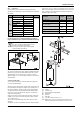
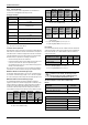
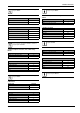
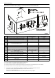
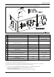
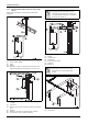
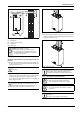
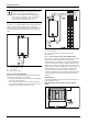
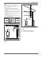
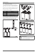
Table Of Contents
- Table of contents
- 1 Key to symbols and safety instructions
- 1.1 Key to symbols
- 1.2 Safety instructions
- 2 FCC rules
- 3 Appliance details
- 4 Installation instructions
- 4.1 Specialized tools
- 4.2 Introduction
- 4.3 Venting
- 4.3.1 Vent options
- 4.3.2 Vent specifications
- Venting specifications
- Condensate drain requirements
- Minimum combustion air and exhaust pipe length
- Maximum combustion air and exhaust pipe length
- Use of elbows
- Calculation example for 3" PVC, CPVC, or ABS venting:
- Calculation example for 4" PP, PVC, CPVC, or ABS venting:
- Calculation example for 2" PVC venting:
- Required direct vent terminal clearances (twin pipe / concentric penetration) for PVC, CPVC, ABS, and PP.
- Required other than direct vent terminal clearances (single pipe penetration) for PVC, CPVC and ABS systems.
- 4.3.3 Vent configuration examples for PP, PVC, CPVC, or ABS systems
- 4.3.4 Vent connections for PP, PVC, CPVC, and ABS systems
- 4.3.5 Connecting the condensate water drain
- 4.3.6 Freeze prevention for PVC, CPVC, and ABS systems
- 4.3.7 Common venting of 2 to 4 units
- 4.3.8 Fan speed adjustment
- 4.4 Combustion air requirements
- 4.5 Proper location for installing your heater
- 4.6 Heater placement and clearances
- 4.7 Hanging appliance on the wall
- 4.8 Mounting installation
- 4.9 Gas piping & connections
- 4.10 Water connections
- 4.11 Water quality
- 4.12 Filling the condensate trap
- 4.13 Domestic hot water recirculation
- 4.14 Space heating applications
- 4.15 Measuring gas pressure
- 5 Electrical connections
- 6 Operation instructions
- 7 Maintenance and service
- 8 Troubleshooting
- 9 Problem solving
- 10 Electrical diagram
- 11 Sensor resistance charts
- 12 Functional scheme
- 13 Interior components diagram
- 14 Protecting the environment
- 15 LIMITED TANKLESS HEATER WARRANTY
- 16 Installer Checklist to be completed by installer upon installation

Installation instructions
RTG 199 HE – 6 720 811 617 (2016/01)
12
4.3.2 Vent specifications
Establish vent clearances that comply with the vent manufacturer's
specifications and all applicable national/local codes.
Venting specifications
[*] ULC S636-95, UL1738 certified
Condensate drain requirements
When the Water Heater is installed in a residential single family dwelling
without direct recirculation an external condensate drain is not required.
If the Water Heater is installed in an application other than a residential
single family dwelling an external condensate drain (not supplied with
the Water Heater) is required in the following circumstances:
• Vertical terminating exhaust vent installations.
• Horizontal terminating exhaust vent installations greater than 6 feet
(1.8 m) linear measurement, (NOT total equivalent length).
• Vent installations where any section of the exhaust vent pipe passes
through an unconditioned space.
Note: An external condensate drain is recommended in all installations
as best practice in order to maximize the longevity of the Water Heater.
Minimum combustion air and exhaust pipe length
The minimum exhaust pipe length is 1 foot (0.3m) of straight vent pipe.
The minimum combustion air pipe length is one 90° elbow, except with
the Common Vent System where the provided air intake grill cap is used.
Maximum combustion air and exhaust pipe length
The following tables display the maximum allowable straight pipe
lengths for combustion air and exhaust piping with consideration to the
number of elbows used. Reduce the equivalent length for each elbow
used from the maximum allowable length depending on the system
used. Refer to table 8 if using 3" diameter venting. Refer to table 9 if
using 4" diameter venting. Refer to table 10 if using 2" diameter venting.
Use of elbows
It is recommended to limit the amount of elbows used in the exhaust and
combustion air piping to reduce friction in the air flow. The following lists
the maximum amount of 90° elbows allowed in either the exhaust or
combustion air piping:
Calculation example for 3" PVC, CPVC, or ABS venting:
Exhaust
Diam. Approved terminals
E
x
h
a
u
s
t
3 or 4 inches “T” terminal
2, 3 or 4 inches 90° elbow
3 inches PVC Flue Cap*(ECAP321)Vertical terminations
3" diameter only
3 or 4 inches Concentric
I
n
t
a
k
e
3 or 4 inches “T” terminal
2, 3 or 4 inches 90° elbow
3 inches PVC Flue Cap*(ECAP321)Vertical & horizontal
terminations approved 3" diameter only
3 or 4 inches Concentric
Table 7 Venting specifications for intake and exhaust
3" Venting
Maximum
allowable
total vent
Length
Maximum
allowable
Exhaust
Length
Maximum
allowable
Intake
Length
Elbow
Equivalency
90° 45°
Twin pipe 62 ft 31ft 31ft 5 ft 2.5 ft
Concentric 46 ft 23ft 23ft 5 ft 2.5 ft
Table 8 Maximum Allowable Exhaust and Combustion Air Lengths for 3"
PP, PVC, CPVC, and ABS venting
4" Venting
Maximum
allowable
total vent
Length
Maximum
allowable
Exhaust
Length
Maximum
allowable
Intake
Length
Elbow
Equivalency
90° 45°
Twin pipe 126ft 63ft 63ft 5ft 2.5ft
Concentric 86ft 43ft 43ft 5ft 2.5ft
Table 9 Maximum Allowable Exhaust and Combustion Air Lengths for 4"
PP, PVC, CPVC, and ABS venting
2" Venting
Maximum
allowable
total vent
Length
Maximum
allowable
Exhaust
Length
Maximum
allowable
Intake
Length
Elbow
Equivalency
90°
1)
1) If using 90° short sweep elbow equivalent length is 5 ft.
If using 90° long sweep elbow equivalent length is 2.5 ft.
45°
Twin pipe
with two
terminations
19ft 9.5ft 9.5ft
5 ft /
2.5 ft
2.5 ft
Table 10 Maximum Allowable Exhaust and Combustion Air Lengths for
2" PVC venting
Max. number of 90° elbows 3" venting 4" venting 2" venting
Twin pipe system 5 7 1 or 2
1)
1) If using 90° short sweep elbow the max. number is 1.
If using 90° long sweep elbow the max. number is 2.
Concentric system 4 7 _
Table 11
Two 45° elbows are equal to one 90° elbow. Any
combination of 45° and 90° elbows may be used in
the vent system as long as the combination does not
exceed the maximum listed in table 11 above.
System used Concentric
Number of 90° elbows needed: 1
Number of 45° elbows needed: 2
Table 12
Calculation of example
Max. length 23’
90° elbow reduction - 5’
sub-total = 18’
45° elbow reduction - 5’
Total = 13’
Table 13