
Installation / Operation Instruction Manual
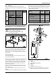
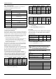
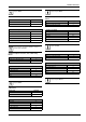
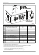
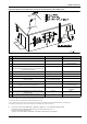
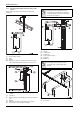
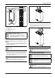
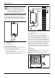
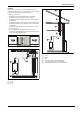
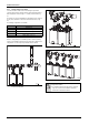
Table Of Contents
- Table of contents
- 1 Key to symbols and safety instructions
- 1.1 Key to symbols
- 1.2 Safety instructions
- 2 FCC rules
- 3 Appliance details
- 4 Installation instructions
- 4.1 Specialized tools
- 4.2 Introduction
- 4.3 Venting
- 4.3.1 Vent options
- 4.3.2 Vent specifications
- Venting specifications
- Condensate drain requirements
- Minimum combustion air and exhaust pipe length
- Maximum combustion air and exhaust pipe length
- Use of elbows
- Calculation example for 3" PVC, CPVC, or ABS venting:
- Calculation example for 4" PP, PVC, CPVC, or ABS venting:
- Calculation example for 2" PVC venting:
- Required direct vent terminal clearances (twin pipe / concentric penetration) for PVC, CPVC, ABS, and PP.
- Required other than direct vent terminal clearances (single pipe penetration) for PVC, CPVC and ABS systems.
- 4.3.3 Vent configuration examples for PP, PVC, CPVC, or ABS systems
- 4.3.4 Vent connections for PP, PVC, CPVC, and ABS systems
- 4.3.5 Connecting the condensate water drain
- 4.3.6 Freeze prevention for PVC, CPVC, and ABS systems
- 4.3.7 Common venting of 2 to 4 units
- 4.3.8 Fan speed adjustment
- 4.4 Combustion air requirements
- 4.5 Proper location for installing your heater
- 4.6 Heater placement and clearances
- 4.7 Hanging appliance on the wall
- 4.8 Mounting installation
- 4.9 Gas piping & connections
- 4.10 Water connections
- 4.11 Water quality
- 4.12 Filling the condensate trap
- 4.13 Domestic hot water recirculation
- 4.14 Space heating applications
- 4.15 Measuring gas pressure
- 5 Electrical connections
- 6 Operation instructions
- 7 Maintenance and service
- 8 Troubleshooting
- 9 Problem solving
- 10 Electrical diagram
- 11 Sensor resistance charts
- 12 Functional scheme
- 13 Interior components diagram
- 14 Protecting the environment
- 15 LIMITED TANKLESS HEATER WARRANTY
- 16 Installer Checklist to be completed by installer upon installation

Installation instructions
RTG 199 HE – 6 720 811 617 (2016/01)
14
Required direct vent terminal clearances (twin pipe / concentric penetration) for PVC, CPVC, ABS, and PP.
Fig. 10
[*] For clearances not specified in ANSI Z223.1 / NFPA 54 or CSA-B149.1, one of the following shall be indicated:
a) A minimum clearance value determined by testing in accordance with section 2.20, or;
b) A reference to the following footnote:
“Clearance in accordance with local installation codes and the requirements of the gas supplier.”
Canadian installations
1)
1) In accordance with the current CSA B149.1 Natural Gas and Propane Installation Code.
U.S. installations
2)
2) In accordance with the current ANSI Z223.1 / NFPA 54 National Fuel Gas Code.
A Clearance above grade, veranda, porch, deck or balcony 12 in. 12 in.
B Clearance to window or door that may be opened 36 in. 12 in.
C Clearance to permanently closed window * *
D Vertical clearance to ventilated soffit located above the vent
termination within a horizontal distance of 2 feet (61cm) from
the center line of the termination
**
E Clearance to unventilated soffit * *
F Clearance to outside corner * *
G Clearance to inside corner * *
H Clearance to each side of center line extended above meter/
regulator assembly
36 in. within a height 15 feet above
meter/ regulator assembly
*
I Clearance to service regulator vent outlet 36 in. *
J Clearance to non-mechanical air supply inlet to building or the
combustion air inlet to any other application
36 in. 12 in.
K Clearance to mechanical air supply inlet 72 in. 36 in. above if within 10 feet
horizontally
L Clearance above paved sidewalk or paved driveway located on
public property
84 in.
3)
3) A vent shall not terminate directly above a sidewalk or paved driveway that is located between two single family dwellings and serves both dwellings.
*
M Clearance under veranda, porch deck or balcony 12 in.
4)
4) Permitted only if veranda, porch, deck or balcony is fully open on a minimum of two sides beneath the floor.
*
Table 24