
Installation / Operation Instruction Manual
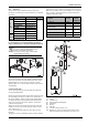
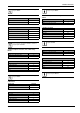
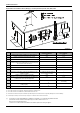
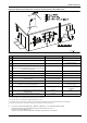
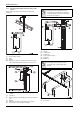
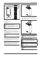
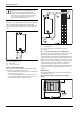
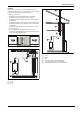
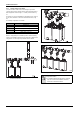
Table Of Contents
- Table of contents
- 1 Key to symbols and safety instructions
- 1.1 Key to symbols
- 1.2 Safety instructions
- 2 FCC rules
- 3 Appliance details
- 4 Installation instructions
- 4.1 Specialized tools
- 4.2 Introduction
- 4.3 Venting
- 4.3.1 Vent options
- 4.3.2 Vent specifications
- Venting specifications
- Condensate drain requirements
- Minimum combustion air and exhaust pipe length
- Maximum combustion air and exhaust pipe length
- Use of elbows
- Calculation example for 3" PVC, CPVC, or ABS venting:
- Calculation example for 4" PP, PVC, CPVC, or ABS venting:
- Calculation example for 2" PVC venting:
- Required direct vent terminal clearances (twin pipe / concentric penetration) for PVC, CPVC, ABS, and PP.
- Required other than direct vent terminal clearances (single pipe penetration) for PVC, CPVC and ABS systems.
- 4.3.3 Vent configuration examples for PP, PVC, CPVC, or ABS systems
- 4.3.4 Vent connections for PP, PVC, CPVC, and ABS systems
- 4.3.5 Connecting the condensate water drain
- 4.3.6 Freeze prevention for PVC, CPVC, and ABS systems
- 4.3.7 Common venting of 2 to 4 units
- 4.3.8 Fan speed adjustment
- 4.4 Combustion air requirements
- 4.5 Proper location for installing your heater
- 4.6 Heater placement and clearances
- 4.7 Hanging appliance on the wall
- 4.8 Mounting installation
- 4.9 Gas piping & connections
- 4.10 Water connections
- 4.11 Water quality
- 4.12 Filling the condensate trap
- 4.13 Domestic hot water recirculation
- 4.14 Space heating applications
- 4.15 Measuring gas pressure
- 5 Electrical connections
- 6 Operation instructions
- 7 Maintenance and service
- 8 Troubleshooting
- 9 Problem solving
- 10 Electrical diagram
- 11 Sensor resistance charts
- 12 Functional scheme
- 13 Interior components diagram
- 14 Protecting the environment
- 15 LIMITED TANKLESS HEATER WARRANTY
- 16 Installer Checklist to be completed by installer upon installation

Installation instructions
RTG 199 HE – 6 720 811 617 (2016/01)
19
Installation
For this solution to be effective, the internal flapper must be 100%
closed when the water heater is not running. Refer to Figures 23 and24
for preferred installation positions in the vent system.
Installation considerations:
• Install damper per the supplied manufacturer‘s instructions.
• The damper is only to be used in the exhaust vent piping.
• Ensure directional arrow on damper label faces in the same direction
as exhaust flow.
• If installed horizontally, the axis must be horizontal or slightly pitched
up towards termination to ensure damper closes 100% when heater
is not running.
• To allow accessibility, damper must not be installed in an enclosed
section of vent pipe.
• Do not install damper in unconditioned spaces (e.g. attics)
Condensation can build up while the heater is running which can later
freeze and potentially block the flapper.
Fig. 22 Blackflow reducer (9301BFP) installed
Fig. 23
[1] Good
[2] Better
[3] Best
Fig. 24
[1] Good
[2] Better
[3] Best
[4] Enclosed vent pipe (Do not install damper)
[5] Unconditioned space (Do not install damper)
[6] Preferred damper position for vertical terminations
6720608643-19.1V