
Installation / Operation Instruction Manual
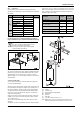
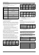
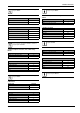
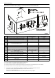
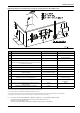
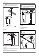
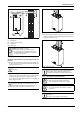
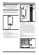
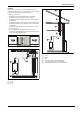
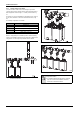
Table Of Contents
- Table of contents
- 1 Key to symbols and safety instructions
- 1.1 Key to symbols
- 1.2 Safety instructions
- 2 FCC rules
- 3 Appliance details
- 4 Installation instructions
- 4.1 Specialized tools
- 4.2 Introduction
- 4.3 Venting
- 4.3.1 Vent options
- 4.3.2 Vent specifications
- Venting specifications
- Condensate drain requirements
- Minimum combustion air and exhaust pipe length
- Maximum combustion air and exhaust pipe length
- Use of elbows
- Calculation example for 3" PVC, CPVC, or ABS venting:
- Calculation example for 4" PP, PVC, CPVC, or ABS venting:
- Calculation example for 2" PVC venting:
- Required direct vent terminal clearances (twin pipe / concentric penetration) for PVC, CPVC, ABS, and PP.
- Required other than direct vent terminal clearances (single pipe penetration) for PVC, CPVC and ABS systems.
- 4.3.3 Vent configuration examples for PP, PVC, CPVC, or ABS systems
- 4.3.4 Vent connections for PP, PVC, CPVC, and ABS systems
- 4.3.5 Connecting the condensate water drain
- 4.3.6 Freeze prevention for PVC, CPVC, and ABS systems
- 4.3.7 Common venting of 2 to 4 units
- 4.3.8 Fan speed adjustment
- 4.4 Combustion air requirements
- 4.5 Proper location for installing your heater
- 4.6 Heater placement and clearances
- 4.7 Hanging appliance on the wall
- 4.8 Mounting installation
- 4.9 Gas piping & connections
- 4.10 Water connections
- 4.11 Water quality
- 4.12 Filling the condensate trap
- 4.13 Domestic hot water recirculation
- 4.14 Space heating applications
- 4.15 Measuring gas pressure
- 5 Electrical connections
- 6 Operation instructions
- 7 Maintenance and service
- 8 Troubleshooting
- 9 Problem solving
- 10 Electrical diagram
- 11 Sensor resistance charts
- 12 Functional scheme
- 13 Interior components diagram
- 14 Protecting the environment
- 15 LIMITED TANKLESS HEATER WARRANTY
- 16 Installer Checklist to be completed by installer upon installation

Installation instructions
RTG 199 HE – 6 720 811 617 (2016/01)
20
4.3.7 Common venting of 2 to 4 units
2 to 4 unit cascades can be common vented using the optional PP
common venting system. The water heaters can be installed in a back to
back configuration as shown in fig. 26, or side by side as shown in fig.
27.
The systems are custom configurable for vent lengths from 40” (1m) up
to 100’ (30m) and either a vertical or horizontal termination (see fig.
25).
The following configurations are available:
Where no empty wall space is available a powder coated steel racking
system is also available for water heaters in side by side or back to back
configurations. See the respective product brochure for details.
Fig. 25 Common venting for 2 to 4 water heaters available with vertical
or horizontal termination
Fig. 26 Back to back configuration
Fig. 27 Side by side configuration
Units Configurations
2 Back to Back
4 Back to Back - see fig. 26
2 Side by Side - see fig. 25
3Side by Side
4 Side by Side - see fig. 27
Table 26
NOTICE: Figures 25 to 27 depict the conceptual
configurations available.
▶ For installation details and requirements consult the
respective common vent installation instructions
listed on the manufacturers website.