
Installation / Operation Instruction Manual
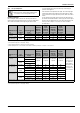
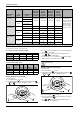
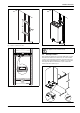
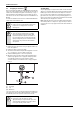
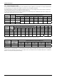
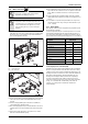
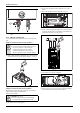
Table Of Contents
- Table of contents
- 1 Key to symbols and safety instructions
- 1.1 Key to symbols
- 1.2 Safety instructions
- 2 FCC rules
- 3 Appliance details
- 4 Installation instructions
- 4.1 Specialized tools
- 4.2 Introduction
- 4.3 Venting
- 4.3.1 Vent options
- 4.3.2 Vent specifications
- Venting specifications
- Condensate drain requirements
- Minimum combustion air and exhaust pipe length
- Maximum combustion air and exhaust pipe length
- Use of elbows
- Calculation example for 3" PVC, CPVC, or ABS venting:
- Calculation example for 4" PP, PVC, CPVC, or ABS venting:
- Calculation example for 2" PVC venting:
- Required direct vent terminal clearances (twin pipe / concentric penetration) for PVC, CPVC, ABS, and PP.
- Required other than direct vent terminal clearances (single pipe penetration) for PVC, CPVC and ABS systems.
- 4.3.3 Vent configuration examples for PP, PVC, CPVC, or ABS systems
- 4.3.4 Vent connections for PP, PVC, CPVC, and ABS systems
- 4.3.5 Connecting the condensate water drain
- 4.3.6 Freeze prevention for PVC, CPVC, and ABS systems
- 4.3.7 Common venting of 2 to 4 units
- 4.3.8 Fan speed adjustment
- 4.4 Combustion air requirements
- 4.5 Proper location for installing your heater
- 4.6 Heater placement and clearances
- 4.7 Hanging appliance on the wall
- 4.8 Mounting installation
- 4.9 Gas piping & connections
- 4.10 Water connections
- 4.11 Water quality
- 4.12 Filling the condensate trap
- 4.13 Domestic hot water recirculation
- 4.14 Space heating applications
- 4.15 Measuring gas pressure
- 5 Electrical connections
- 6 Operation instructions
- 7 Maintenance and service
- 8 Troubleshooting
- 9 Problem solving
- 10 Electrical diagram
- 11 Sensor resistance charts
- 12 Functional scheme
- 13 Interior components diagram
- 14 Protecting the environment
- 15 LIMITED TANKLESS HEATER WARRANTY
- 16 Installer Checklist to be completed by installer upon installation

Installation instructions
RTG 199 HE – 6 720 811 617 (2016/01)
22
PP Concentric up and out venting - RTG 199 HE
Cascade common venting system
Adjusting minimum power fan speed (P2)
To select fan speed:
▶ Press ON/OFF button into ON.
▶ Immediately following, press and hold simultaneously buttons
or and for 3 seconds, until display reads P2.
Fig. 28
▶ Press to enter P2 adjustment. The current setting will appear on
the display (factory default).
▶ Press or to choose the fan speed suitable with your
installation, see table 28 and table 29.
▶ Press and hold ( 5 sec.) “Program” button until the display
flashes, then the selected value is memorized.
Adjusting maximum power fan speed (P1)
To select fan speed:
▶ Press ON/OFF button into ON.
▶ Immediately following, press and hold simultaneously buttons
or and for 3 seconds, until display reads P2.
Fig. 29
▶ Press the minus button to display P1.
▶ Press “Program” button to enter P1 adjustment. The current
setting will appear on the display.
▶ Press or to choose the fan speed suitable with your
installation, see table28 and table 29.
Natural Gas
Liquid
propane Natural Gas
Liquid
propane
Altitude (above
sea level)
Vent
terminal
Total equivalent vent
length
1)
Minimum
power fan
speed (P2)
Minimum
power fan
speed (P2)
Maximum
power fan
speed (P1)
Maximum
power fan
speed (P1)
0 - 2000 ft
(0 - 610 m)
Concentric 3.5 - 39 ft No
modification
required
No
modification
required
No
modification
required
No
modification
required
For operation at
elevations above
2,000 ft (610 m) the
equipment ratings
shall be reduced at
the rate of 4% for
each 1,000 ft (305
m) above sea level
40 - 86 ft
Twin
system
3.5 - 59 ft
60 - 126 ft
2000 - 4500 ft
(610 - 1372 m)
Concentric 3.5 - 39 ft 11* 14* 52* 52*
40 - 86 ft 11* 14* 53* 53*
Twin
system
3.5 - 59 ft 10* 13* 52* 52*
60 - 126 ft 11* 14* 53* 53*
4500 - 8000 ft
(1372 - 2439 m)
Concentric 3.5 - 39 ft 11* 14* 53* 53*
40 - 86 ft 13* 16* 53* 53*
Twin
system
3.5 - 59 ft 11* 14* 53* 53*
60 - 126 ft 12* 15* 53* 53*
* Above 2000 ft, CO2 levels must be checked with a combustion gas analyzer, see chapter 7.5 for instructions.
Table 29 Fan speed adjustment for 4" piping
1) Full equivalent length (inlet + outlet piping + fittings)
Altitude NG P2 LP P2 NG P1 LP P1
0 - 2000 no change no change no change 50
2000 - 4500 no change no change no change 50
4500 - 8000 no change no change no change 50
Table 30 Fan speed adjustment for concentric up and out vent
Altitude
Total
equivalent
length
NG P2 LP P2 NG P1 LP P1
0 - 2000 4 - 100ft 19 19 no change no change
2000 - 4500 4 - 100ft 20 20 52 53
4500 - 8000 4 - 100ft 20 20 53 53
Table 31 Fan speed adjustment for cascade vent
+
P
Proceed directly to chapter 7.5 to confirm CO
2
values
are within range.
P
+
P
+
P
P
+