
Installation / Operation Instruction Manual
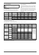
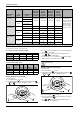
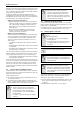
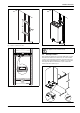
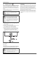
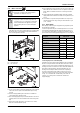
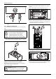
Table Of Contents
- Table of contents
- 1 Key to symbols and safety instructions
- 1.1 Key to symbols
- 1.2 Safety instructions
- 2 FCC rules
- 3 Appliance details
- 4 Installation instructions
- 4.1 Specialized tools
- 4.2 Introduction
- 4.3 Venting
- 4.3.1 Vent options
- 4.3.2 Vent specifications
- Venting specifications
- Condensate drain requirements
- Minimum combustion air and exhaust pipe length
- Maximum combustion air and exhaust pipe length
- Use of elbows
- Calculation example for 3" PVC, CPVC, or ABS venting:
- Calculation example for 4" PP, PVC, CPVC, or ABS venting:
- Calculation example for 2" PVC venting:
- Required direct vent terminal clearances (twin pipe / concentric penetration) for PVC, CPVC, ABS, and PP.
- Required other than direct vent terminal clearances (single pipe penetration) for PVC, CPVC and ABS systems.
- 4.3.3 Vent configuration examples for PP, PVC, CPVC, or ABS systems
- 4.3.4 Vent connections for PP, PVC, CPVC, and ABS systems
- 4.3.5 Connecting the condensate water drain
- 4.3.6 Freeze prevention for PVC, CPVC, and ABS systems
- 4.3.7 Common venting of 2 to 4 units
- 4.3.8 Fan speed adjustment
- 4.4 Combustion air requirements
- 4.5 Proper location for installing your heater
- 4.6 Heater placement and clearances
- 4.7 Hanging appliance on the wall
- 4.8 Mounting installation
- 4.9 Gas piping & connections
- 4.10 Water connections
- 4.11 Water quality
- 4.12 Filling the condensate trap
- 4.13 Domestic hot water recirculation
- 4.14 Space heating applications
- 4.15 Measuring gas pressure
- 5 Electrical connections
- 6 Operation instructions
- 7 Maintenance and service
- 8 Troubleshooting
- 9 Problem solving
- 10 Electrical diagram
- 11 Sensor resistance charts
- 12 Functional scheme
- 13 Interior components diagram
- 14 Protecting the environment
- 15 LIMITED TANKLESS HEATER WARRANTY
- 16 Installer Checklist to be completed by installer upon installation

Installation instructions
RTG 199 HE – 6 720 811 617 (2016/01)
25
Fig. 30 Distance between support boards
[1] Studs 16" (406mm) on center
Fig. 31 Leveling wall mounting bracket
Fig. 32 Mounting the heater
4.8 Mounting installation
When installing this appliance the unit must be additionally secured at
the bottom of the water heater as shown in fig. 33. Use the included
screws to secure the brackets at the bottom of the water heater to the
wall. If the wall is sheathed with plaster or drywall, it is recommended
that a support board be first attached across a pair of studs at the
bottom of the unit as shown in fig. 30.
Fig. 33 Mounting the heater
CAUTION: Personal injury and property damage.
▶ Appliance must be installed vertically.