
Installation / Operation Instruction Manual
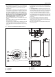
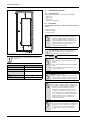
Table Of Contents
- Table of contents
- 1 Key to symbols and safety instructions
- 1.1 Key to symbols
- 1.2 Safety instructions
- 2 FCC rules
- 3 Appliance details
- 4 Installation instructions
- 4.1 Specialized tools
- 4.2 Introduction
- 4.3 Venting
- 4.3.1 Vent options
- 4.3.2 Vent specifications
- Venting specifications
- Condensate drain requirements
- Minimum combustion air and exhaust pipe length
- Maximum combustion air and exhaust pipe length
- Use of elbows
- Calculation example for 3" PVC, CPVC, or ABS venting:
- Calculation example for 4" PP, PVC, CPVC, or ABS venting:
- Calculation example for 2" PVC venting:
- Required direct vent terminal clearances (twin pipe / concentric penetration) for PVC, CPVC, ABS, and PP.
- Required other than direct vent terminal clearances (single pipe penetration) for PVC, CPVC and ABS systems.
- 4.3.3 Vent configuration examples for PP, PVC, CPVC, or ABS systems
- 4.3.4 Vent connections for PP, PVC, CPVC, and ABS systems
- 4.3.5 Connecting the condensate water drain
- 4.3.6 Freeze prevention for PVC, CPVC, and ABS systems
- 4.3.7 Common venting of 2 to 4 units
- 4.3.8 Fan speed adjustment
- 4.4 Combustion air requirements
- 4.5 Proper location for installing your heater
- 4.6 Heater placement and clearances
- 4.7 Hanging appliance on the wall
- 4.8 Mounting installation
- 4.9 Gas piping & connections
- 4.10 Water connections
- 4.11 Water quality
- 4.12 Filling the condensate trap
- 4.13 Domestic hot water recirculation
- 4.14 Space heating applications
- 4.15 Measuring gas pressure
- 5 Electrical connections
- 6 Operation instructions
- 7 Maintenance and service
- 8 Troubleshooting
- 9 Problem solving
- 10 Electrical diagram
- 11 Sensor resistance charts
- 12 Functional scheme
- 13 Interior components diagram
- 14 Protecting the environment
- 15 LIMITED TANKLESS HEATER WARRANTY
- 16 Installer Checklist to be completed by installer upon installation

Key to symbols and safety instructions
RTG 199 HE – 6 720 811 617 (2016/01)
3
1 Key to symbols and safety instructions
1.1 Key to symbols
Warnings
The following keywords are defined and can be used in this document:
• NOTICE indicates that damage to property may occur.
• CAUTION indicates that personal injury may occur.
• WARNING indicates that severe personal injury may occur.
• DANGER indicates that severe personal injury or death may occur.
Important information
Additional symbols
1.2 Safety instructions
Read all instructions before installing. Perform the steps in the indicated
sequence. Have the water heater inspected by a trained service
technician at least once every year. Failure to comply with these
instructions can result in severe, possibly fatal, personal injury as well as
damage to property and equipment.
Installation and servicing
▶ Risk of fire when soldering and brazing!
Take appropriate protective measures when soldering and brazing
around combustible and flammable material.
▶ Ensure that only a licensed contractor installs or services the water
heater.
▶ On hot components use only material with adequate temperature
stability.
Installation and commissioning
▶ In the Commonwealth of Massachusetts, the water heater must be
installed by a licensed plumber.
▶ Do not install this device in rooms with a high moisture level
(e.g. bathrooms, saunas).
Function
▶ To ensure that the water heater functions properly, follow these
installation and maintenance instructions.
▶ Never close the blow-off line of the T&P safety valve. For safety
reasons, water may escape during heating.
If you smell gas
▶ Turn off the gas shut-off valve.
▶ Open windows and doors.
▶ Do not try to light the appliance.
▶ Do not touch any electrical switch, telephone, and do not use outlets.
▶ Extinguish all open flames. Do not smoke! Do not use lighters!
▶ Warn all occupants of the building. Do not ring doorbells!
▶ If you can hear gas leaking, leave the building immediately.
▶ Prevent others from entering the building and notify the police and
fire department from outside the building.
▶ From outside the building, call the gas utility company and a trained
and certified installer.
If you smell flue gas
▶ Switch off the appliance.
▶ Open windows and doors.
▶ Inform a trained and certified installer.
Insufficient ventilation may cause toxic flue gas to escape. Risk of
poisoning.
▶ Never close off or reduce the size of the air intake and outlet
openings.
▶ The appliance must not be operated until any obstructions have been
removed.
▶ Inform the system operator in writing of the problem and the
associated dangers.
Danger from escaping flue gases
▶ Ensure all vent pipes and chimneys are not damaged or blocked.
▶ Connect only one appliance to each vent system or chimney liner.
▶ The venting system piping must not feed into another air extraction
duct.
▶ Do not route the flue system piping through or inside another air
extraction duct.
Danger of explosion of flammable gases
▶ Work on gas components may only be carried out by a trained and
certified installer.
▶ Installation, gas and flue connection, initial commissioning, electrical
connections and annual maintenance must only be carried out by a
trained and certified installer.
Combustion air
▶ Keep the combustion air free of corrosive substances (halogenated
hydrocarbons that contain chlorine or fluorine compounds).
Never shut off safety valves!
▶ Water may escape from the safety valve at any time when the water
is being heated.
Inspection/maintenance
▶ Servicing and repairs may only be carried out by a trained and
certified installer.
▶ Immediately correct all faults to prevent system damage.
▶ Use only Bradford White spare parts! Damage caused by the use of
parts not supplied by Bradford White may void the warranty.
Instruct the customer
▶ Explain to the customer how the appliance works and how to operate
it.
▶ Inform the customer that he/she must not carry out any alterations or
repairs.
Danger from electric shock
▶ Ensure that only an authorized contractor performs electrical work.
▶ Before performing electrical work, disconnect the power and secure
the unit against unintentional reconnection.
▶ Ensure the system has been disconnected from the power supply.
Warnings in this document are identified by a warning
triangle printed against a grey background.
Keywords at the start of a warning indicate the type and
seriousness of the ensuing risk if measures to prevent
the risk are not taken.
This symbol indicates important information where
there is no risk to people or property.
Symbol Explanation
▶ Step in an action sequence
Cross-reference to another part of the document
• List entry
– List entry (second level)
Table 1