
Installation / Operation Instruction Manual
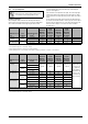
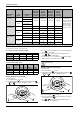
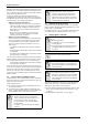
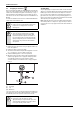
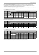
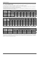
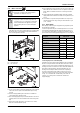
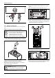
Table Of Contents
- Table of contents
- 1 Key to symbols and safety instructions
- 1.1 Key to symbols
- 1.2 Safety instructions
- 2 FCC rules
- 3 Appliance details
- 4 Installation instructions
- 4.1 Specialized tools
- 4.2 Introduction
- 4.3 Venting
- 4.3.1 Vent options
- 4.3.2 Vent specifications
- Venting specifications
- Condensate drain requirements
- Minimum combustion air and exhaust pipe length
- Maximum combustion air and exhaust pipe length
- Use of elbows
- Calculation example for 3" PVC, CPVC, or ABS venting:
- Calculation example for 4" PP, PVC, CPVC, or ABS venting:
- Calculation example for 2" PVC venting:
- Required direct vent terminal clearances (twin pipe / concentric penetration) for PVC, CPVC, ABS, and PP.
- Required other than direct vent terminal clearances (single pipe penetration) for PVC, CPVC and ABS systems.
- 4.3.3 Vent configuration examples for PP, PVC, CPVC, or ABS systems
- 4.3.4 Vent connections for PP, PVC, CPVC, and ABS systems
- 4.3.5 Connecting the condensate water drain
- 4.3.6 Freeze prevention for PVC, CPVC, and ABS systems
- 4.3.7 Common venting of 2 to 4 units
- 4.3.8 Fan speed adjustment
- 4.4 Combustion air requirements
- 4.5 Proper location for installing your heater
- 4.6 Heater placement and clearances
- 4.7 Hanging appliance on the wall
- 4.8 Mounting installation
- 4.9 Gas piping & connections
- 4.10 Water connections
- 4.11 Water quality
- 4.12 Filling the condensate trap
- 4.13 Domestic hot water recirculation
- 4.14 Space heating applications
- 4.15 Measuring gas pressure
- 5 Electrical connections
- 6 Operation instructions
- 7 Maintenance and service
- 8 Troubleshooting
- 9 Problem solving
- 10 Electrical diagram
- 11 Sensor resistance charts
- 12 Functional scheme
- 13 Interior components diagram
- 14 Protecting the environment
- 15 LIMITED TANKLESS HEATER WARRANTY
- 16 Installer Checklist to be completed by installer upon installation

Installation instructions
RTG 199 HE – 6 720 811 617 (2016/01)
30
Fig. 37 Plumbing Connections (with shutoff valves) and Pressure Relief
Valve
4.12 Filling the condensate trap
The condensate trap can be filled before or after connecting the vent
pipe.
Filling the condensate trap before vent pipe installation
▶ Fill the condensate trap by pouring approx.14 oz. (400ml) of water
into the exhaust accessory on the top of the appliance, see fig. 38.
Fig. 38 Filling the condensate trap at start up
Filling the condensate trap after vent pipe installation
After appliance has been out of use for a long time or after cleaning
siphon, refill the condensate trap with water.
Please proceed as follows:
▶ Remove front cover, see fig. 4, page 8.
▶ Open the four clips and remove the combustion cover, see fig. 5,
page 8.
▶ Remove the clip and disconnect the drain tube, see fig. 39.
Fig. 39 Disconnect drain tube
▶ Fill the condensate trap by pouring approx.14 oz. (400ml) of water
into the top of the drain tube. To avoid damage to the appliance use
a funnel in this operation, see fig. 40, page 30.
Fig. 40 Filling the condensate trap after installation
▶ Loosen the three screws of the control unit.
Fig. 41
▶ Put the control unit in service position by engaging its tabs with the
holes in the bottom horizontal sheet metal, see fig. 42.
DANGER: Flue gas poisoning!
▶ Prior to initial start up, and after appliance has been
out of use for a long time or after cleaning the
condensate trap, make sure that you fill the
condensate trap with water. This is to prevent
dangerous exhaust gases from entering the building.
CAUTION: Electric shock!
▶ Disconnect power to water heater by unplugging
from wall outlet prior to filling condensate trap.