
Installation / Operation Instruction Manual
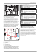
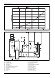
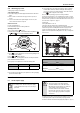
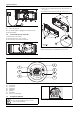
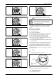
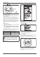
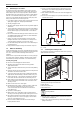
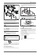
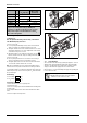
Table Of Contents
- Table of contents
- 1 Key to symbols and safety instructions
- 1.1 Key to symbols
- 1.2 Safety instructions
- 2 FCC rules
- 3 Appliance details
- 4 Installation instructions
- 4.1 Specialized tools
- 4.2 Introduction
- 4.3 Venting
- 4.3.1 Vent options
- 4.3.2 Vent specifications
- Venting specifications
- Condensate drain requirements
- Minimum combustion air and exhaust pipe length
- Maximum combustion air and exhaust pipe length
- Use of elbows
- Calculation example for 3" PVC, CPVC, or ABS venting:
- Calculation example for 4" PP, PVC, CPVC, or ABS venting:
- Calculation example for 2" PVC venting:
- Required direct vent terminal clearances (twin pipe / concentric penetration) for PVC, CPVC, ABS, and PP.
- Required other than direct vent terminal clearances (single pipe penetration) for PVC, CPVC and ABS systems.
- 4.3.3 Vent configuration examples for PP, PVC, CPVC, or ABS systems
- 4.3.4 Vent connections for PP, PVC, CPVC, and ABS systems
- 4.3.5 Connecting the condensate water drain
- 4.3.6 Freeze prevention for PVC, CPVC, and ABS systems
- 4.3.7 Common venting of 2 to 4 units
- 4.3.8 Fan speed adjustment
- 4.4 Combustion air requirements
- 4.5 Proper location for installing your heater
- 4.6 Heater placement and clearances
- 4.7 Hanging appliance on the wall
- 4.8 Mounting installation
- 4.9 Gas piping & connections
- 4.10 Water connections
- 4.11 Water quality
- 4.12 Filling the condensate trap
- 4.13 Domestic hot water recirculation
- 4.14 Space heating applications
- 4.15 Measuring gas pressure
- 5 Electrical connections
- 6 Operation instructions
- 7 Maintenance and service
- 8 Troubleshooting
- 9 Problem solving
- 10 Electrical diagram
- 11 Sensor resistance charts
- 12 Functional scheme
- 13 Interior components diagram
- 14 Protecting the environment
- 15 LIMITED TANKLESS HEATER WARRANTY
- 16 Installer Checklist to be completed by installer upon installation

Installation instructions
RTG 199 HE – 6 720 811 617 (2016/01)
31
▶ Check water level in the condensate trap.
Fig. 42 Water level in condensate trap
▶ After filling reassemble all parts in reverse order.
4.13 Domestic hot water recirculation
Although recirculation directly through the tankless water heater is
allowed, temperature stability is improved by recirculating through a
tank as shown in fig. 43. By using the design in fig. 43, there is no
recirculation of hot water through the tankless water heater and
therefore, does not affect the heat exchanger warranty. Direct
recirculation through the tankless water heater is permissible, however,
the heat exchanger warranty is reduced; contact manufacturer for
further installation requirements. The following drawing is provided to
outline one possible recirculation design using the water heater in
conjunction with an electric storage water heater. This schematic is for
illustration only and must not be used for actual Installation without
appropriate engineering and technical advice from a properly licensed
professional in the locality where the installation is made.
Fig. 43 Recirculation application
[1] Full port isolation valve
[2] Circulator pump on timer
[3] Check valve
[4] PRV
[5] Expansion tank
[6] Tankless water heater
[7] Electric storage water heater
The use of a small electric tank after heater (4-6 gallon size) should be
used for this application and designed so the pump will circulate the
water through the tank and the building's hot water return loop only.
Timed or thermostatically controlled operation of the pump is commonly
done. Contact manufacturer if further information is needed.
4.14 Space heating applications
Bradford White tankless water heaters are approved for use in
combination DHW and space heating applications (open-loop setup).
These water heaters are not approved for use in space heating only
applications (closed-loop setup). Applications of combination DHW and
space heating in an open loop configuration is acceptable if plumbed
similar to fig. 45. Use of a this tankless water heater in a combination
DHW and space heating application will result in the product warranty
being reduced to 3 years.
CAUTION:
▶ If the set point temperature is above 120°F,
precautions should be taken to protect users of
potable water from scalding.
CAUTION:
▶ Propylene glycol may be used for freeze prevention
ONLY on the space heating side of the heat
exchanger. Do not use ethylene glycol (automotive
antifreeze).
CAUTION:
▶ The use of a flow switch is recommended to ensure
DHW priority and to prevent “cold-blow” situations
when the tankless water heater is used with an air-
handling system. The flow switch should be used to
disable the blower on the air-handling system when
domestic water is used.
CAUTION:
▶ Ensure the primary pump is properly sized to provide
adequate flow for the system heat load. Ensure the
primary pump is properly sized to provide adequate
flow for the system heat load.
For Pump sizing please refer to the pressure drop
curves, fig. 44. Also remember to account for system
piping pressure loss. A minimum of 1.7 GPM is
recommended to provide adequate flow through the
water heater when determining the size of the primary
pump.