
Installation / Operation Instruction Manual
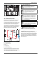
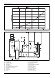
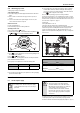
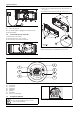
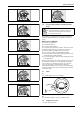
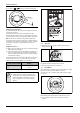
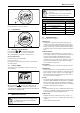
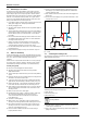
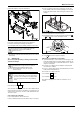
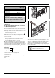
Table Of Contents
- Table of contents
- 1 Key to symbols and safety instructions
- 1.1 Key to symbols
- 1.2 Safety instructions
- 2 FCC rules
- 3 Appliance details
- 4 Installation instructions
- 4.1 Specialized tools
- 4.2 Introduction
- 4.3 Venting
- 4.3.1 Vent options
- 4.3.2 Vent specifications
- Venting specifications
- Condensate drain requirements
- Minimum combustion air and exhaust pipe length
- Maximum combustion air and exhaust pipe length
- Use of elbows
- Calculation example for 3" PVC, CPVC, or ABS venting:
- Calculation example for 4" PP, PVC, CPVC, or ABS venting:
- Calculation example for 2" PVC venting:
- Required direct vent terminal clearances (twin pipe / concentric penetration) for PVC, CPVC, ABS, and PP.
- Required other than direct vent terminal clearances (single pipe penetration) for PVC, CPVC and ABS systems.
- 4.3.3 Vent configuration examples for PP, PVC, CPVC, or ABS systems
- 4.3.4 Vent connections for PP, PVC, CPVC, and ABS systems
- 4.3.5 Connecting the condensate water drain
- 4.3.6 Freeze prevention for PVC, CPVC, and ABS systems
- 4.3.7 Common venting of 2 to 4 units
- 4.3.8 Fan speed adjustment
- 4.4 Combustion air requirements
- 4.5 Proper location for installing your heater
- 4.6 Heater placement and clearances
- 4.7 Hanging appliance on the wall
- 4.8 Mounting installation
- 4.9 Gas piping & connections
- 4.10 Water connections
- 4.11 Water quality
- 4.12 Filling the condensate trap
- 4.13 Domestic hot water recirculation
- 4.14 Space heating applications
- 4.15 Measuring gas pressure
- 5 Electrical connections
- 6 Operation instructions
- 7 Maintenance and service
- 8 Troubleshooting
- 9 Problem solving
- 10 Electrical diagram
- 11 Sensor resistance charts
- 12 Functional scheme
- 13 Interior components diagram
- 14 Protecting the environment
- 15 LIMITED TANKLESS HEATER WARRANTY
- 16 Installer Checklist to be completed by installer upon installation

Electrical connections
RTG 199 HE – 6 720 811 617 (2016/01)
33
4.15 Measuring gas pressure
Confirm gas pressure upon installation.
Connecting manometer
▶ Shut off gas supply at installer supplied shutoff valve for this water
heater.
▶ Remove front cover and locate inlet gas pressure test port (see
Fig.47).
▶ Loosen screw inside left test point fitting (do not remove) and
connect manometer tube to test point.
Static Pressure Test
▶ Turn gas supply back on.
▶ Record static gas pressure reading in table 40.
Operating Pressure Test
▶ Press ON/OFF button into ON.
▶ Immediately following, press and hold simultaneously buttons
or and for 3 seconds, until display reads P2.
Fig. 46
▶ Press to enter P2 adjustment. The current setting will appear on
the display (factory default).
▶ Press or until P1 appears.
Note: While in this mode the appliance will run constantly at maximum
power and allow maximum water flow.
For inlet gas pressure adjustment consider the following table:
▶ Operate all other gas appliances (except heater) on same gas piping
system at maximum output.
▶ Turn on high volume of hot water flow (at least 6 gpm, 1 tub and 2
sinks should be sufficient) and burner will light. If heater display
reverts to P2, open more hot water fixtures to allow sufficient flow.
Press until P1 reappears on the display.
▶ Record lowest operating gas pressure reading in table 40.
Gas pressures lower than 3.5" W.C. for Natural Gas or 8" W.C. for LPG
will result in insufficient degree rise to the hot water being used, reduced
hot water volume, possible error code faults and must be corrected. See
Gas Connections, chapter 4.9, page 26.
P1 fan speed:
Factory default: NG: 51, LP: 52
Lowering P1 fan speed reduces the maximum BTU input.
As a temporary measure if the gas pressure in P1 is below specification,
lower P1 fan speed incrementally until minimum inlet gas pressure
reaches specified range (table 39). After upgrading gas line, reset
appliance to P1 factory default setting (NG: 51, LP: 52) or setting from
Section 4.3.8.
Fig. 47 Gas pressure test port (left tapping)
5 Electrical connections
5.1 Electrical power supply
The water heater requires an electrical power supply from a 120VAC /
60Hz properly rated receptacle and must be properly grounded.
The heater is wired as shown in the wiring diagram (chapter 10, Fig.75).
Gas type NG LPG
p
in
3.5” WC 8” WC
Table 39 Minimum inlet gas pressure under full operation
+
P
P
+
Static Gas Pressure Reading (see chapter 4.15)
enter here: ___________________ Date: ___________
Operating Gas Pressure Reading (see chapter 4.15)
enter here: ___________________ Date: ___________
Table 40
+
6720608920-16.1AL
WARNING:
▶ For safety reasons, disconnect the power supply
cord to the heater before any service or testing is
performed.
WARNING:
▶ This heater must be electrically grounded in
accordance with the most recent edition of the
National Electrical Code. NFPA 70. In Canada, all
electrical wiring to the heater must be in
accordance with local codes and the Canadian
Electrical Code, CSA C22.1 Part 1. Do not rely on
the gas or water piping to ground the metal parts
of the heater.