
Installation / Operation Instruction Manual
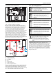
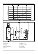
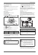
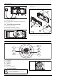
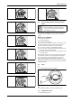
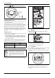
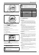
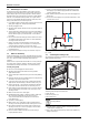
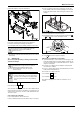
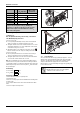
Table Of Contents
- Table of contents
- 1 Key to symbols and safety instructions
- 1.1 Key to symbols
- 1.2 Safety instructions
- 2 FCC rules
- 3 Appliance details
- 4 Installation instructions
- 4.1 Specialized tools
- 4.2 Introduction
- 4.3 Venting
- 4.3.1 Vent options
- 4.3.2 Vent specifications
- Venting specifications
- Condensate drain requirements
- Minimum combustion air and exhaust pipe length
- Maximum combustion air and exhaust pipe length
- Use of elbows
- Calculation example for 3" PVC, CPVC, or ABS venting:
- Calculation example for 4" PP, PVC, CPVC, or ABS venting:
- Calculation example for 2" PVC venting:
- Required direct vent terminal clearances (twin pipe / concentric penetration) for PVC, CPVC, ABS, and PP.
- Required other than direct vent terminal clearances (single pipe penetration) for PVC, CPVC and ABS systems.
- 4.3.3 Vent configuration examples for PP, PVC, CPVC, or ABS systems
- 4.3.4 Vent connections for PP, PVC, CPVC, and ABS systems
- 4.3.5 Connecting the condensate water drain
- 4.3.6 Freeze prevention for PVC, CPVC, and ABS systems
- 4.3.7 Common venting of 2 to 4 units
- 4.3.8 Fan speed adjustment
- 4.4 Combustion air requirements
- 4.5 Proper location for installing your heater
- 4.6 Heater placement and clearances
- 4.7 Hanging appliance on the wall
- 4.8 Mounting installation
- 4.9 Gas piping & connections
- 4.10 Water connections
- 4.11 Water quality
- 4.12 Filling the condensate trap
- 4.13 Domestic hot water recirculation
- 4.14 Space heating applications
- 4.15 Measuring gas pressure
- 5 Electrical connections
- 6 Operation instructions
- 7 Maintenance and service
- 8 Troubleshooting
- 9 Problem solving
- 10 Electrical diagram
- 11 Sensor resistance charts
- 12 Functional scheme
- 13 Interior components diagram
- 14 Protecting the environment
- 15 LIMITED TANKLESS HEATER WARRANTY
- 16 Installer Checklist to be completed by installer upon installation

Operation instructions
RTG 199 HE – 6 720 811 617 (2016/01)
34
Fig. 48 Connecting power supply cord
[1] Power cord length: 3ft.
Note: The outlet the appliance is plugged into should be clear from
possible water damage.
5.2 Position of the fuses in control unit
To check fuses, proceed as follows:
▶ Remove the front cover, see fig. 4, page 8.
▶ Remove the three screws from the control unit.
Fig. 49
▶ Remove the six screws from the back cover of the control unit, see
fig. 50, pos. 2.
▶ Check the fuses in the printed circuit board, see fig. 50, pos. 3.
Fig. 50 Fuses position
▶ After checking the fuses, reinstall all parts in reverse order.
6 Operation instructions
Fig. 51
[1] On/Off button
[2] Reset button
[3] Program Key
[4] LCD display
[5] Up button
[6] Down button
[7] Power On or stand-by LED
6.1 Description LCD Display
Fig. 52 Power bar indicator (input)
2
3
1
5
4
6
7
6720608920-10.1AL
WARNING:
▶ Do not use any cleaning aggressive or corrosive
agents to clean the window.