
Installation / Operation Instruction Manual
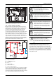
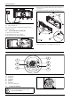
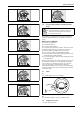
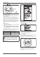
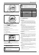
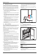
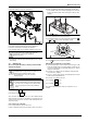
Table Of Contents
- Table of contents
- 1 Key to symbols and safety instructions
- 1.1 Key to symbols
- 1.2 Safety instructions
- 2 FCC rules
- 3 Appliance details
- 4 Installation instructions
- 4.1 Specialized tools
- 4.2 Introduction
- 4.3 Venting
- 4.3.1 Vent options
- 4.3.2 Vent specifications
- Venting specifications
- Condensate drain requirements
- Minimum combustion air and exhaust pipe length
- Maximum combustion air and exhaust pipe length
- Use of elbows
- Calculation example for 3" PVC, CPVC, or ABS venting:
- Calculation example for 4" PP, PVC, CPVC, or ABS venting:
- Calculation example for 2" PVC venting:
- Required direct vent terminal clearances (twin pipe / concentric penetration) for PVC, CPVC, ABS, and PP.
- Required other than direct vent terminal clearances (single pipe penetration) for PVC, CPVC and ABS systems.
- 4.3.3 Vent configuration examples for PP, PVC, CPVC, or ABS systems
- 4.3.4 Vent connections for PP, PVC, CPVC, and ABS systems
- 4.3.5 Connecting the condensate water drain
- 4.3.6 Freeze prevention for PVC, CPVC, and ABS systems
- 4.3.7 Common venting of 2 to 4 units
- 4.3.8 Fan speed adjustment
- 4.4 Combustion air requirements
- 4.5 Proper location for installing your heater
- 4.6 Heater placement and clearances
- 4.7 Hanging appliance on the wall
- 4.8 Mounting installation
- 4.9 Gas piping & connections
- 4.10 Water connections
- 4.11 Water quality
- 4.12 Filling the condensate trap
- 4.13 Domestic hot water recirculation
- 4.14 Space heating applications
- 4.15 Measuring gas pressure
- 5 Electrical connections
- 6 Operation instructions
- 7 Maintenance and service
- 8 Troubleshooting
- 9 Problem solving
- 10 Electrical diagram
- 11 Sensor resistance charts
- 12 Functional scheme
- 13 Interior components diagram
- 14 Protecting the environment
- 15 LIMITED TANKLESS HEATER WARRANTY
- 16 Installer Checklist to be completed by installer upon installation

Operation instructions
RTG 199 HE – 6 720 811 617 (2016/01)
35
Fig. 53 Temperature indicator
Fig. 54 Error indicator
Fig. 55 Locked condition indicator (only with remote control)
Fig. 56 Flame indicator
Fig. 57 Solar mode indicator (see chapter 6.4, page 35)
Fig. 58 Remote control indicator
Fig. 59 Activation water flow (see chapter 12)
6.2 For your safety read before operating your water
heater
A. This appliance is equipped with electronic ignition for lighting the
main burner. When turning the heater on, follow these instructions
exactly.
WHAT TO DO IF YOU SMELL GAS
▶ Turn off the gas shut-off valve.
▶ Open windows and doors.
▶ Do not try to light the appliance.
▶ Do not touch any electrical switch, telephone, and do not use outlets.
▶ Extinguish all open flames. Do not smoke! Do not use lighters!
▶ Warn all occupants of the building. Do not ring doorbells!
▶ If you can hear gas leaking, leave the building immediately.
▶ Prevent others from entering the building and notify the police and
fire department from outside the building.
▶ From outside the building, call the gas utility company and a trained
and certified installer.
B. Use only your hand to press the on/off control switch. Never use tools.
If control switch is jammed, close the gas supply and call a qualified
service technician. Forceful repair may result in a fire or explosion.
C. Do not use this appliance if any part has been under water.
Immediately call a qualified service technician to inspect the appliance
and to replace any part of the control system and any gas control which
has been under water.
6.3 Power
On
▶ To start the appliance press the On/Off button.
Fig. 60
Off
▶ To shut down the appliance press the On/Off button again.
6.4 Temperature selection
To select hot water temperature:
DANGER: Explosion hazard!
▶ If you do not follow these instructions exactly, a fire
or explosion may result causing property damage,
personal injury or loss of life.
6720608920-11.1AL