
Installation / Operation Instruction Manual
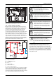
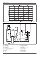
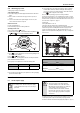
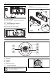
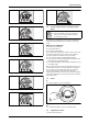
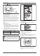
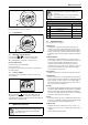
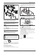
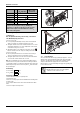
Table Of Contents
- Table of contents
- 1 Key to symbols and safety instructions
- 1.1 Key to symbols
- 1.2 Safety instructions
- 2 FCC rules
- 3 Appliance details
- 4 Installation instructions
- 4.1 Specialized tools
- 4.2 Introduction
- 4.3 Venting
- 4.3.1 Vent options
- 4.3.2 Vent specifications
- Venting specifications
- Condensate drain requirements
- Minimum combustion air and exhaust pipe length
- Maximum combustion air and exhaust pipe length
- Use of elbows
- Calculation example for 3" PVC, CPVC, or ABS venting:
- Calculation example for 4" PP, PVC, CPVC, or ABS venting:
- Calculation example for 2" PVC venting:
- Required direct vent terminal clearances (twin pipe / concentric penetration) for PVC, CPVC, ABS, and PP.
- Required other than direct vent terminal clearances (single pipe penetration) for PVC, CPVC and ABS systems.
- 4.3.3 Vent configuration examples for PP, PVC, CPVC, or ABS systems
- 4.3.4 Vent connections for PP, PVC, CPVC, and ABS systems
- 4.3.5 Connecting the condensate water drain
- 4.3.6 Freeze prevention for PVC, CPVC, and ABS systems
- 4.3.7 Common venting of 2 to 4 units
- 4.3.8 Fan speed adjustment
- 4.4 Combustion air requirements
- 4.5 Proper location for installing your heater
- 4.6 Heater placement and clearances
- 4.7 Hanging appliance on the wall
- 4.8 Mounting installation
- 4.9 Gas piping & connections
- 4.10 Water connections
- 4.11 Water quality
- 4.12 Filling the condensate trap
- 4.13 Domestic hot water recirculation
- 4.14 Space heating applications
- 4.15 Measuring gas pressure
- 5 Electrical connections
- 6 Operation instructions
- 7 Maintenance and service
- 8 Troubleshooting
- 9 Problem solving
- 10 Electrical diagram
- 11 Sensor resistance charts
- 12 Functional scheme
- 13 Interior components diagram
- 14 Protecting the environment
- 15 LIMITED TANKLESS HEATER WARRANTY
- 16 Installer Checklist to be completed by installer upon installation

Operation instructions
RTG 199 HE – 6 720 811 617 (2016/01)
36
▶ Press buttons or in order to reach desired temperature.
Fig. 61
Setting the water temperature
The desired temperature of the hot water can be adjusted on the front
control panel of the heater.
The water heater has an electronically controlled gas valve that
modulates the burner input in response to both varying hot water flow
rates and/or changes in any incoming and outgoing water temperatures.
Note: The water heater, running at minimum BTU, may still achieve
temperatures above the desired set temperature. Low flowing fixtures
are the leading cause of this type of temperature overshoot. To combat
this symptom, clean fixtures or replace with higher flowing ones if
necessary.
Saving water resources:
▶ Make sure you close all the taps after any use. Avoid leaving the taps
dripping. Repair any leaking tap.
▶ Define the temperature you want, in the appliance or with the remote
control. This way you have the precise water flow needed (mixing
cold water to regulate temperature will increase the water flow with
consequent waste of water).
The water heater will not ignite if inlet water temperature exceeds the set
point temperature less 9 °F (5 °C). In this condition, the solar mode
indicator will show on the LCD display. See fig. 57, page 35.
Fig. 62
6.5 Operation
▶ When a hot water tap is opened, main burner ignites and LCD
displays indication .
Fig. 63
▶ LCD flashes until selected temperature is reached.
▶ Power bar indicates power percentage in use.
6.6 Reset button
If the LCD shows the error symbol do not shut off power or unplug
the heater. Follow instructions below to reset error first.
Record the error code on LCD and consult “Problem solving” chapter
9.1, page 44.
Fig. 64
After following instructions indicated in “Troubleshooting” section,
▶ press reset button firmly in order to return heater to normal
operation.
Solar mode activation formula Example:
Temp. inlet > Temp. set - 9 °F
(5 °C)
104 °F (40 °C) > 112 °F (44 °C) -
9 °F (5 °C)
Table 41
WARNING: Appliance damage!
▶ In applications where inlet water temperature can
exceed 140°F (60°C), a thermostatic or mixing valve
must be installed before the appliance to prevent
water exceeding 140°F (60°C) from entering the
appliance.
+
6720608920-12.1AL
6720608920-14.1AL