
Installation / Operation Instruction Manual
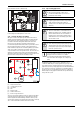
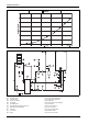
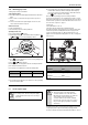
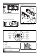
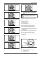
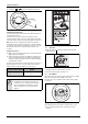
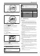
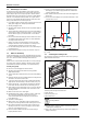
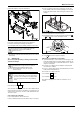
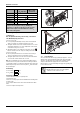
Table Of Contents
- Table of contents
- 1 Key to symbols and safety instructions
- 1.1 Key to symbols
- 1.2 Safety instructions
- 2 FCC rules
- 3 Appliance details
- 4 Installation instructions
- 4.1 Specialized tools
- 4.2 Introduction
- 4.3 Venting
- 4.3.1 Vent options
- 4.3.2 Vent specifications
- Venting specifications
- Condensate drain requirements
- Minimum combustion air and exhaust pipe length
- Maximum combustion air and exhaust pipe length
- Use of elbows
- Calculation example for 3" PVC, CPVC, or ABS venting:
- Calculation example for 4" PP, PVC, CPVC, or ABS venting:
- Calculation example for 2" PVC venting:
- Required direct vent terminal clearances (twin pipe / concentric penetration) for PVC, CPVC, ABS, and PP.
- Required other than direct vent terminal clearances (single pipe penetration) for PVC, CPVC and ABS systems.
- 4.3.3 Vent configuration examples for PP, PVC, CPVC, or ABS systems
- 4.3.4 Vent connections for PP, PVC, CPVC, and ABS systems
- 4.3.5 Connecting the condensate water drain
- 4.3.6 Freeze prevention for PVC, CPVC, and ABS systems
- 4.3.7 Common venting of 2 to 4 units
- 4.3.8 Fan speed adjustment
- 4.4 Combustion air requirements
- 4.5 Proper location for installing your heater
- 4.6 Heater placement and clearances
- 4.7 Hanging appliance on the wall
- 4.8 Mounting installation
- 4.9 Gas piping & connections
- 4.10 Water connections
- 4.11 Water quality
- 4.12 Filling the condensate trap
- 4.13 Domestic hot water recirculation
- 4.14 Space heating applications
- 4.15 Measuring gas pressure
- 5 Electrical connections
- 6 Operation instructions
- 7 Maintenance and service
- 8 Troubleshooting
- 9 Problem solving
- 10 Electrical diagram
- 11 Sensor resistance charts
- 12 Functional scheme
- 13 Interior components diagram
- 14 Protecting the environment
- 15 LIMITED TANKLESS HEATER WARRANTY
- 16 Installer Checklist to be completed by installer upon installation

Maintenance and service
RTG 199 HE – 6 720 811 617 (2016/01)
37
Fig. 65 Reset button
If the problem persists, contact your installer.
6.7 Program button
Fig. 66 “Program” key
6.7.1 Memorizing selected temperature
▶ Press buttons or to select desired temperature.
▶ Hold “Program” button for 3 seconds to save temperature.
When LCD stops blinking, temperature is saved in memory.
Using “Program” function
In order to select memorized temperature
▶ Press “Program” key.
LCD shows pre-memorized temperature, which is now the hot water
selected temperature.
6.8 Locked condition
This condition is only valid for appliances with one or more remote
controls installed.
Fig. 67 Locked condition
Whenever LCD shows , the temperature setting cannot be
adjusted because the appliance is in use by a user which already
selected a different temperature. Appliance will be automatically unlock
5 minutes after closing hot water tap.
7 Maintenance and service
7.1 Annual maintenance
(To remove front cover, see page 8.)
Venting System
• Venting system - inspect inside of flue pipe for any blockage or
restriction. Observe burner flames during heater operation. (front
cover must be removed). Inspect the combustion air inlet pipe for
blockage or debris. Inspect combustion air and exhaust terminations
for blockage or debris. Inspect combustion chamber for blockage or
debris.
Combustion Chamber
• Inspect burner observation window (Fig.79, #14, page 51) for
cracks or spillage of flue gases. Observe burner flames during heater
operation. Flames should be steady and blue with no signs of
yellowing. Yellow burner flames are an indication of improper
combustion. Refer to Section 4.4, page 23, chapter 4.3, page 10 of
this manual to verify exhaust system and combustion air supply
meets manufacturer's specifications.
Pressure Relief
• Manually open the pressure relief valve to ensure proper operation.
Inlet Water Filter
• Verify the inlet filter screen is clean and undamaged. The inlet water
filter is located on the bottom of the appliance, to the right of the cold
water inlet fitting. (See Fig.36, page 29). Close installer supplied
water shutoff and remove wireform spring clip from filter. Remove
filter, clean and or replace if damaged.
Descaling
• In areas where the water supply has a high mineral content, the heat
exchanger should be flushed with a descaling solution. Scale build up
will shorten the life of the water heater and damage resulting from
scale is not covered under warranty. Refer to section7.3 for detailed
instructions on descaling the heat exchanger.
Fin Coils
• Inspect heat exchanger fin coils for soot build-up or blockage. If there
is evidence of soot build-up or blockage, the heat exchanger should
be removed by a professional and cleaned thoroughly.
Condensate trap
• Check water level in the condensate trap, see fig. 42, page 31.
• If appliance is out of service for more than 10 days, fill as described
on page 30.
• Check for debris and clean if needed.
DANGER:
▶ Always shut off the electrical power supply, shut off
the manual gas valve and shut off the water valves
whenever servicing.
6720608920-15.1AL
+
NOTICE:
▶ Inspect and clean the complete water heating system
once a year.
▶ Carry out a maintenance as necessary. Immediately
repair all faults to avoid damage to the system.
Annual maintenance table
Every year
1. Inspect venting system X
2. Inspect combustion chamber X
3. Inspect burner X
4. Inspect condensate trap X
5. Inspect water filter X
Table 42 Annual maintenance