
Installation / Operation Instruction Manual
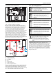
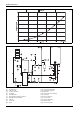
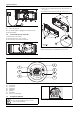
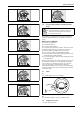
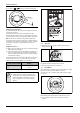
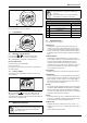
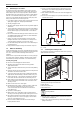
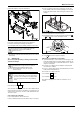
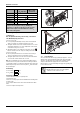
Table Of Contents
- Table of contents
- 1 Key to symbols and safety instructions
- 1.1 Key to symbols
- 1.2 Safety instructions
- 2 FCC rules
- 3 Appliance details
- 4 Installation instructions
- 4.1 Specialized tools
- 4.2 Introduction
- 4.3 Venting
- 4.3.1 Vent options
- 4.3.2 Vent specifications
- Venting specifications
- Condensate drain requirements
- Minimum combustion air and exhaust pipe length
- Maximum combustion air and exhaust pipe length
- Use of elbows
- Calculation example for 3" PVC, CPVC, or ABS venting:
- Calculation example for 4" PP, PVC, CPVC, or ABS venting:
- Calculation example for 2" PVC venting:
- Required direct vent terminal clearances (twin pipe / concentric penetration) for PVC, CPVC, ABS, and PP.
- Required other than direct vent terminal clearances (single pipe penetration) for PVC, CPVC and ABS systems.
- 4.3.3 Vent configuration examples for PP, PVC, CPVC, or ABS systems
- 4.3.4 Vent connections for PP, PVC, CPVC, and ABS systems
- 4.3.5 Connecting the condensate water drain
- 4.3.6 Freeze prevention for PVC, CPVC, and ABS systems
- 4.3.7 Common venting of 2 to 4 units
- 4.3.8 Fan speed adjustment
- 4.4 Combustion air requirements
- 4.5 Proper location for installing your heater
- 4.6 Heater placement and clearances
- 4.7 Hanging appliance on the wall
- 4.8 Mounting installation
- 4.9 Gas piping & connections
- 4.10 Water connections
- 4.11 Water quality
- 4.12 Filling the condensate trap
- 4.13 Domestic hot water recirculation
- 4.14 Space heating applications
- 4.15 Measuring gas pressure
- 5 Electrical connections
- 6 Operation instructions
- 7 Maintenance and service
- 8 Troubleshooting
- 9 Problem solving
- 10 Electrical diagram
- 11 Sensor resistance charts
- 12 Functional scheme
- 13 Interior components diagram
- 14 Protecting the environment
- 15 LIMITED TANKLESS HEATER WARRANTY
- 16 Installer Checklist to be completed by installer upon installation

Maintenance and service
RTG 199 HE – 6 720 811 617 (2016/01)
38
7.2 Winterizing for seasonal use
The water heater must not be installed in a location where it may be
exposed to freezing temperatures. If the heater must be left in a space
which is likely to experience freezing temperatures, all water must be
drained from the heater. If precautions are not taken, resulting damage
will not be covered under the warranty. NOTE: Use of agents such as
anti-freeze is not permitted and voids the warranty, as they may cause
damage to the water heater's internal components.
1. Press ON/OFF switch on the water heater to turn OFF the heater and
unplug power supply cord. The display should be blank.
2. Shut off gas supply to heater.
3. Shut off the water supply to the water heater using installer supplied
shutoff valve.
4. Open hot water taps to drain and relieve pressure from the plumbing
system. If water continues to flow after 5 minutes, a crossover of the
hot and cold water pipes is present and must be corrected before
proceeding.
5. Disconnect inlet and outlet water pipes from the water heater. Place
a small bucket underneath the water heater to catch residual water
remaining inside the water heater.
6. Using an air compressor, blow short bursts of air (100psi max)
through the inlet water connection until there is no water present
coming through the outlet water connection of the heater.
7. Reconnect water fittings and return heater to service when danger of
freezing has passed.
8. Empty condensate trap by removing lower condensate trap cover.
7.3 Mineral scale build-up
Periodic descaling may be necessary in areas with high mineral content
in the water. Scale buildup in the heat exchanger may result in lower flow
rates, error codes of A7 and E9 and boiling sounds in the heat
exchanger.
A water softener is required if the water hardness exceeds 6 grains/gal
(103 mg/l) calcium carbonate. Damage to the water heater resulting
from hard water/scale deposits will not be covered under warranty.
Descaling using a pump
▶ Disconnect electrical supply from the water heater.
▶ Shut off the water supply to the water heater using (installer
supplied) shutoff valve.
▶ Open hot water taps to drain and relieve pressure from the plumbing
system.
▶ Drain water from the unit's heat exchanger by disconnecting inlet and
outlet water connections from the heater.
▶ Connect a line (A) from the outlet of the circulating pump (installer
supplied) to the inlet water fitting on the water heater (see fig. 68.)
▶ Using another line (B), connect the water outlet fitting on the water
heater. Route the other end of this line into a descaling reservoir.
▶ Using a 3rd line (C) from the descaling reservoir, connect to the inlet
side of circulating pump. Install a filter on the end of the line in the
descaling reservoir.
▶ Make sure all connections are "water tight.".
▶ Fill tank with descaling solution so both lines inside are submersed.
We recommend a straight white vinegar solution. If using a
commercial descalant, refer to manufacturer's instructions for
proper dilution ratio.
▶ Operate the circulating pump.
▶ Make sure there are no leaks and the solution is flowing from the
descaling reservoir through the heater and returning to the reservoir.
▶ Run solution through the heater until the solution returning to the
descaling reservoir comes out clear. (Changing to a fresh solution
may be necessary during this process).
▶ Disconnect all lines and drain all solution from heat exchanger.
Properly discard of solution.
▶ Position a container below the hot water outlet and connect cold
water supply. Open cold water supply shutoff valve and flush heat
exchanger with clean water.
▶ Shut cold water shutoff valve and reconnect hot water supply to the
water heater.
▶ Reconnect electrical supply to unit, open water shutoff valves, and
return the unit to service.
Fig. 68
[1] Pump
7.4 Condensing heat exchanger unit
The condensing heat exchanger unit must be checked once a year by a
qualified and trained technician.
Fig. 69 Condensing heat exchanger unit
Condensing heat exchanger unit maintenance;
▶ Shut off power.
▶ Disconnect power cord.
▶ Drain water heater.
▶ Dismantle all inlet, outlet pipes and the condensate tube from the
condensing heat exchanger unit.
▶ Remove the condensing heat exchanger unit from the appliance by
pulling it towards you.
Note: be sure to remove condensing heat exchanger rear
mounting hardware.