
Installation / Operation Instruction Manual
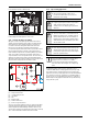
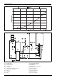
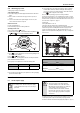
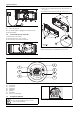
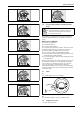
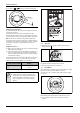
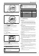
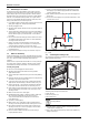
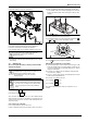
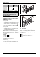
Table Of Contents
- Table of contents
- 1 Key to symbols and safety instructions
- 1.1 Key to symbols
- 1.2 Safety instructions
- 2 FCC rules
- 3 Appliance details
- 4 Installation instructions
- 4.1 Specialized tools
- 4.2 Introduction
- 4.3 Venting
- 4.3.1 Vent options
- 4.3.2 Vent specifications
- Venting specifications
- Condensate drain requirements
- Minimum combustion air and exhaust pipe length
- Maximum combustion air and exhaust pipe length
- Use of elbows
- Calculation example for 3" PVC, CPVC, or ABS venting:
- Calculation example for 4" PP, PVC, CPVC, or ABS venting:
- Calculation example for 2" PVC venting:
- Required direct vent terminal clearances (twin pipe / concentric penetration) for PVC, CPVC, ABS, and PP.
- Required other than direct vent terminal clearances (single pipe penetration) for PVC, CPVC and ABS systems.
- 4.3.3 Vent configuration examples for PP, PVC, CPVC, or ABS systems
- 4.3.4 Vent connections for PP, PVC, CPVC, and ABS systems
- 4.3.5 Connecting the condensate water drain
- 4.3.6 Freeze prevention for PVC, CPVC, and ABS systems
- 4.3.7 Common venting of 2 to 4 units
- 4.3.8 Fan speed adjustment
- 4.4 Combustion air requirements
- 4.5 Proper location for installing your heater
- 4.6 Heater placement and clearances
- 4.7 Hanging appliance on the wall
- 4.8 Mounting installation
- 4.9 Gas piping & connections
- 4.10 Water connections
- 4.11 Water quality
- 4.12 Filling the condensate trap
- 4.13 Domestic hot water recirculation
- 4.14 Space heating applications
- 4.15 Measuring gas pressure
- 5 Electrical connections
- 6 Operation instructions
- 7 Maintenance and service
- 8 Troubleshooting
- 9 Problem solving
- 10 Electrical diagram
- 11 Sensor resistance charts
- 12 Functional scheme
- 13 Interior components diagram
- 14 Protecting the environment
- 15 LIMITED TANKLESS HEATER WARRANTY
- 16 Installer Checklist to be completed by installer upon installation

Maintenance and service
RTG 199 HE – 6 720 811 617 (2016/01)
39
▶ Dismantle all parts for inspection and cleaning.
Fig. 70 Condensing heat exchanger
▶ Check the condensing heat exchanger for any obstruction.
▶ Flush the condensing heat exchanger unit with water.
▶ Check all gasket and o-rings for damage and replace if necessary.
▶ Assemble the condensate unit and all other parts in reverse order of
disassembly.
7.5 Adjusting CO2
The CO2 can only be adjusted by a certified gas technician with a
calibrated CO2 analyzer.
Static Gas Pressure: “ WC
P1 Operating Pressure: “ WC
The P1 minimum operating gas pressure is 3.5" WC for Natural Gas and
8" WC for Propane. Do not proceed in adjusting CO
2
until pressure is at
or above these levels, but not to exceed 10.5" WC for Natural Gas and
13" WC for Propane.
A. Once Gas Pressure is adequate
▶ Press ON/OFF button to turn OFF the heater.
▶ Remove brass flat head screw on the exhaust collar as seen in Fig.71.
▶Insert CO
2
analyzer probe into the measuring port. The tip of the
probe should be in the center of the flue pipe (approx 1.5" inserted).
Avoid air gaps between probe and measuring port as they can alter
readings.
Fig. 71 Measuring port
▶ Press the ON/OFF button to turn ON the heater.
▶ Immediately following, press and hold simultaneously buttons
or and for 3 seconds, until display reads P2.
Fig. 72
▶ Press button until “P1” appears on display.
B. Measuring CO
2
(Combustion cover Installed):
▶ Open all hot water taps to achieve a flow rate of at least 6 gpm. (1 tub
and 2 sinks should be sufficient). If heater display reverts back to P2,
open more hot water fixtures to allow sufficient flow. Press + until P1
reappears on the display.
▶ Record the CO
2
reading in P1 below. (Analyzer reading may take
several minutes to stabilize).
▶ Press the ‘+’ button until P2 appears. Unit will ramp down to low fire
and the water flow should decrease.
▶ Record the CO
2
reading in P2 below.
P1 CO
2
Reading: % CO
2
P2 CO
2
Reading: % CO
2
Note: When making adjustments, make sure combustion cover is
installed.
It is important to inspect and properly replace the
gaskets and o-rings using the available kit
(8 704 701 116 0).
CO
2
adjustment is required in Natural Gas
installations where energy content is less than 900
BTU/cuft, and in installations with repeated
unresolved EA and EC errors (ref. to page 44
“Problem solving”).
CAUTION:
▶ One factor that may affect CO
2
levels is improper gas
pressure. Please see Chapter 4.15 for the procedure
to measure gas pressure and record your findings
below:
+
P