
Installation / Operation Instruction Manual
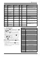
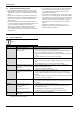
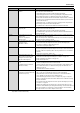
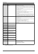
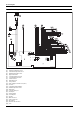
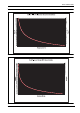
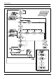
Table Of Contents
- Table of contents
- 1 Key to symbols and safety instructions
- 1.1 Key to symbols
- 1.2 Safety instructions
- 2 FCC rules
- 3 Appliance details
- 4 Installation instructions
- 4.1 Specialized tools
- 4.2 Introduction
- 4.3 Venting
- 4.3.1 Vent options
- 4.3.2 Vent specifications
- Venting specifications
- Condensate drain requirements
- Minimum combustion air and exhaust pipe length
- Maximum combustion air and exhaust pipe length
- Use of elbows
- Calculation example for 3" PVC, CPVC, or ABS venting:
- Calculation example for 4" PP, PVC, CPVC, or ABS venting:
- Calculation example for 2" PVC venting:
- Required direct vent terminal clearances (twin pipe / concentric penetration) for PVC, CPVC, ABS, and PP.
- Required other than direct vent terminal clearances (single pipe penetration) for PVC, CPVC and ABS systems.
- 4.3.3 Vent configuration examples for PP, PVC, CPVC, or ABS systems
- 4.3.4 Vent connections for PP, PVC, CPVC, and ABS systems
- 4.3.5 Connecting the condensate water drain
- 4.3.6 Freeze prevention for PVC, CPVC, and ABS systems
- 4.3.7 Common venting of 2 to 4 units
- 4.3.8 Fan speed adjustment
- 4.4 Combustion air requirements
- 4.5 Proper location for installing your heater
- 4.6 Heater placement and clearances
- 4.7 Hanging appliance on the wall
- 4.8 Mounting installation
- 4.9 Gas piping & connections
- 4.10 Water connections
- 4.11 Water quality
- 4.12 Filling the condensate trap
- 4.13 Domestic hot water recirculation
- 4.14 Space heating applications
- 4.15 Measuring gas pressure
- 5 Electrical connections
- 6 Operation instructions
- 7 Maintenance and service
- 8 Troubleshooting
- 9 Problem solving
- 10 Electrical diagram
- 11 Sensor resistance charts
- 12 Functional scheme
- 13 Interior components diagram
- 14 Protecting the environment
- 15 LIMITED TANKLESS HEATER WARRANTY
- 16 Installer Checklist to be completed by installer upon installation

Maintenance and service
RTG 199 HE – 6 720 811 617 (2016/01)
41
7.7 Control board diagnostics
1. Press ON/OFF button into ON.
2. Immediately following, press and hold simultaneously buttons
or and for 3 seconds, until display reads P2.
3. Press to enter P2 adjustment. The current setting will appear on
the display. If not, repeat process.
4. Press and release the button on the control panel until the
display reads 'P4'. You are now in the diagnostic mode of the control
board.
5. When the display reads 'P4', press and release the button once
again and the display should read 'E'.
6. Use the and button on the control board to cycle through
different diagnostic modes available.
7. Once in the selected diagnostic mode of your choice, press and
release the button to display the diagnostic information.
EXAMPLE: to read the flow rate in gallons per minute while the unit is
flowing water, cycle to the '3d' mode and press the button. A
reading of 25 on the display would indicate the heater is reading a flow
rate of 2.5 gallons/minute.
8. Once the information is obtained, press the button again to
return to the diagnostic mode menu and scroll to addition diagnostic
information.
9. Press ON/OFF button to turn OFF the appliance and back ON again to
return heater to normal function.
Program Description Factory Default MIN MAX Comment
P0 By-pass calibration - - - Contact manufacturer for details.
P1 Maximum Power NG: 51,
LP: 52
21 NG: 53,
LP: 53
see chapter 4.15, page 33
note: reducing P1 values below maximum will
reduce maximum power of the appliance.
P2 Minimum Power NG: 10,
LP: 13
NG: 8,
LP: 11
20 see chapter 4.3.8, page 21
P3 Remote
Controls installed
_0 _0 6 Not available
P4 Access to
Diagnostic Mode
E 0d 10f see chapter 7.7, page 41
P5 Cascade Mode NO NO CC Contact manufacturer for details.
P6 Temperature Unit °F °F °C
P7 Gas type selection LP or NG Preset from factory.
Contact manufacturer for details.
P8 Back light dE dE On dE turns back light off after 60 seconds from
last button pushed, ON turns backlight on
permanently.
P9 Fan Purge Runs secondary fan and primary fan when P9
is selected by depressing the “P” - button
PH Cascading type IC IC SC This menu is only available when cascade
mode is selected CC.
Contact manufacturer for details.
PC Primary/Secondary
mode
CS CS Cn
Table 44 Program values, factory default settings and ranges.
+
P
P
P
+
+
P
P
P
Diagnostic menu
E Entry/Exit into sub-modes
0d Heat exchanger water temperature
1d Inlet water temperature (°F)
2d Outlet water temperature (°F)
3d Water flow (gallons/min)
4d Bypass control monitor (°F) [0d - 2d]
5d Fan speed (Hz)
6d Burner power (%)
7d Maximum power (kW)
8d Back flow temperature (°C)
9d Exhaust temperature (°C)
1F Most recent error/failure
2F 2nd most recent error
3F 3rd most recent error
4F 4th most recent error
5F 5th most recent error
6F 6th most recent error
7F 7th most recent error
8F 8th most recent error
9F 9th most recent error
Table 45 * Settings define from factory