
Installation / Operation Instruction Manual
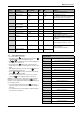
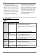
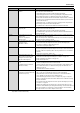
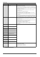
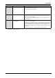
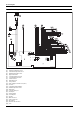
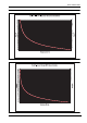
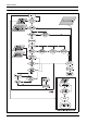
Table Of Contents
- Table of contents
- 1 Key to symbols and safety instructions
- 1.1 Key to symbols
- 1.2 Safety instructions
- 2 FCC rules
- 3 Appliance details
- 4 Installation instructions
- 4.1 Specialized tools
- 4.2 Introduction
- 4.3 Venting
- 4.3.1 Vent options
- 4.3.2 Vent specifications
- Venting specifications
- Condensate drain requirements
- Minimum combustion air and exhaust pipe length
- Maximum combustion air and exhaust pipe length
- Use of elbows
- Calculation example for 3" PVC, CPVC, or ABS venting:
- Calculation example for 4" PP, PVC, CPVC, or ABS venting:
- Calculation example for 2" PVC venting:
- Required direct vent terminal clearances (twin pipe / concentric penetration) for PVC, CPVC, ABS, and PP.
- Required other than direct vent terminal clearances (single pipe penetration) for PVC, CPVC and ABS systems.
- 4.3.3 Vent configuration examples for PP, PVC, CPVC, or ABS systems
- 4.3.4 Vent connections for PP, PVC, CPVC, and ABS systems
- 4.3.5 Connecting the condensate water drain
- 4.3.6 Freeze prevention for PVC, CPVC, and ABS systems
- 4.3.7 Common venting of 2 to 4 units
- 4.3.8 Fan speed adjustment
- 4.4 Combustion air requirements
- 4.5 Proper location for installing your heater
- 4.6 Heater placement and clearances
- 4.7 Hanging appliance on the wall
- 4.8 Mounting installation
- 4.9 Gas piping & connections
- 4.10 Water connections
- 4.11 Water quality
- 4.12 Filling the condensate trap
- 4.13 Domestic hot water recirculation
- 4.14 Space heating applications
- 4.15 Measuring gas pressure
- 5 Electrical connections
- 6 Operation instructions
- 7 Maintenance and service
- 8 Troubleshooting
- 9 Problem solving
- 10 Electrical diagram
- 11 Sensor resistance charts
- 12 Functional scheme
- 13 Interior components diagram
- 14 Protecting the environment
- 15 LIMITED TANKLESS HEATER WARRANTY
- 16 Installer Checklist to be completed by installer upon installation

Problem solving
RTG 199 HE – 6 720 811 617 (2016/01)
45
C6 Primary fan rotation too low in
operation.
1. Disconnect power supply cord and check wire connection on back side of fan and
the connectors on the control board.
2. Check supply voltage. It must be 120VAC and properly grounded.
3. Check venting specifications are met. Long vent lengths, venting with more than
three elbows, blocked vent or combination venting may cause this failure.
4. Ensure intake and exhaust terminations maintain the required clearances stated in
the manual. Cross contamination between intake and exhaust may cause the fan to
alter its rotational speed.
5. Check gas pressure, see chapter 4.15, page 33. Low gas pressure may cause the
fan to change its speed to meet desired temperature.
6. Possible defective control unit call manufacturer for further instructions.
C7 No rotational speed sensor signal
from primary fan.
1. Disconnect power supply cord and check wire connections on back side of fan and
the two connectors on the control board.
2. Check supply voltage. It must be 120VAC and properly grounded.
3. Possible defective component in fan or defective control unit call manufacturer for
further instructions.
(Flashing)
CA
Water flow signal over specified
maximum value.
Water flow > 10 gallon/min.
(Status message).
1. Disconnect power supply cord and check wire connections on water valve and the
two connectors on the control board.
2. Excessive water pressure and flow. Ensure water pressure is less than 150psi and
flow rate is below 10 gallons per minute.
E1 Over-temperature detected by outlet
temperature sensor.
Temperature > 185°F
1. Check wire connection at outlet temperature sensor.
2. In areas where water has a high mineral content, periodic descaling may be
necessary. See chapter7.3, page 38 for directions.
3. Check sensor (ref. page 48, chapter 10).
E2 Inlet temperature sensor fault. 1. Check wire connection at inlet temperature sensor, see fig. 79, page 51.
2. Sensor may trip if water temperature drops below 36°F (2°C). Protect heater from
freezing conditions as any damage due to freezing conditions is not covered under
warranty.
3. Check sensor (ref. page 49, chapter 11).
E3 Exhaust temperature sensor - the
appliance will close the burner and
lock if it gets over 194°F; (only
applied for condensing unit).
1. Clean and check heat exchanger. See chapter 7.1, page 37.
2. Clean and check condensing heat exchanger. See chapter 7.4, page 38.
3. Reduce maximum power (chapter 4.15, page 33).
4. Reduce water temperature.
E4 Backflow temperature sensor over
309°F.
The appliance will close the burner
and lock (non-volatile).
1. Check inlet/outlet vent pipes.
2. Check if secondary fan connections are disconnected.
3. Check if venting specifications are met. Long vent lengths, venting with more than
three elbows, blocked vent or combination venting may cause this failure. See
chapter 4.3, page 10.
4. Call manufacturer for further instructions.
E9 Overheat sensor (ECO) open circuit
(resets when cooler temperatures are
detected 220°F/104 °C).
1. Disconnect power supply cord and check wire connections on the overheat sensor
(fig. 79, #12, page 51) and the two connectors on the control board.
2. Check white wire connections at the overheat sensor. Clean terminals with an
eraser. If badly corroded, replace sensor and wire harness.
3. Check that venting specifications are met, see chapter 4.3. page 10. Long vent
lengths, venting with more than three elbows, blocked vent or combination venting
may cause this failure.
4. In areas where water has a high mineral content, periodic descaling may necessary,
see chapter 7.3, page 38.
5. Unplug power supply cord to the water heater. Open a hot water tap for several
minutes to allow cold water to pass through heat exchanger. Close hot water tap and
disconnect lead wires to overheat sensor. Using a multimeter, check continuity
through overheat sensor contacts. Replace sensor if open.
Display Cause Solution
Table 49
* By installer or service technician only.