
Installation / Operation Instruction Manual
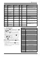
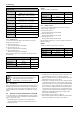
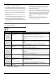
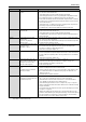
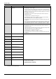
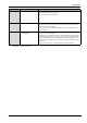
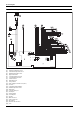
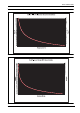
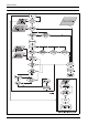
Table Of Contents
- Table of contents
- 1 Key to symbols and safety instructions
- 1.1 Key to symbols
- 1.2 Safety instructions
- 2 FCC rules
- 3 Appliance details
- 4 Installation instructions
- 4.1 Specialized tools
- 4.2 Introduction
- 4.3 Venting
- 4.3.1 Vent options
- 4.3.2 Vent specifications
- Venting specifications
- Condensate drain requirements
- Minimum combustion air and exhaust pipe length
- Maximum combustion air and exhaust pipe length
- Use of elbows
- Calculation example for 3" PVC, CPVC, or ABS venting:
- Calculation example for 4" PP, PVC, CPVC, or ABS venting:
- Calculation example for 2" PVC venting:
- Required direct vent terminal clearances (twin pipe / concentric penetration) for PVC, CPVC, ABS, and PP.
- Required other than direct vent terminal clearances (single pipe penetration) for PVC, CPVC and ABS systems.
- 4.3.3 Vent configuration examples for PP, PVC, CPVC, or ABS systems
- 4.3.4 Vent connections for PP, PVC, CPVC, and ABS systems
- 4.3.5 Connecting the condensate water drain
- 4.3.6 Freeze prevention for PVC, CPVC, and ABS systems
- 4.3.7 Common venting of 2 to 4 units
- 4.3.8 Fan speed adjustment
- 4.4 Combustion air requirements
- 4.5 Proper location for installing your heater
- 4.6 Heater placement and clearances
- 4.7 Hanging appliance on the wall
- 4.8 Mounting installation
- 4.9 Gas piping & connections
- 4.10 Water connections
- 4.11 Water quality
- 4.12 Filling the condensate trap
- 4.13 Domestic hot water recirculation
- 4.14 Space heating applications
- 4.15 Measuring gas pressure
- 5 Electrical connections
- 6 Operation instructions
- 7 Maintenance and service
- 8 Troubleshooting
- 9 Problem solving
- 10 Electrical diagram
- 11 Sensor resistance charts
- 12 Functional scheme
- 13 Interior components diagram
- 14 Protecting the environment
- 15 LIMITED TANKLESS HEATER WARRANTY
- 16 Installer Checklist to be completed by installer upon installation

Problem solving
RTG 199 HE – 6 720 811 617 (2016/01)
46
EA No flame ionization detected with
water flow.
1. Verify that all manual gas shut off valves are open.
2. Check gas type. See fig. 2, page 7.
3. Reset error code and open a water tap to cycle the heater in an effort to purge air.
Cycling hot water tap on and off multiple times may be necessary. If heater still faults
with EA error code, have a licensed gas technician properly purge air out of the gas
line leading to the water heater.
4. Check three wire connections to ignition group on the lower front of the heat
exchanger are secure.
5. Check gas pressure. See chapter 4.15, page 33.
6. Check venting specifications are met. Improper venting may cause premature
failure of the flame sensor rod. See chapter 4.3, page 10.
7. Check that the minimum power fan speed has been adjusted to the proper value.
See page 21.
8. Observe inside the viewing window of the heat exchanger when a hot water tap is
opened. Sparking should be followed by a steady blue flame. If flame is unstable/
yellow with proper gas pressure, confirm CO
2
readings per chapter 7.5, page 39.
EC Ionization failure during operation. 1. Check gas type, fig. 2, page 7.
2. Check three wire connections to ignition group on the lower front of the heat
exchanger are secure.
3. Verify that venting specifications are met. Improper venting may cause premature
failure of the flame sensor rod. See chapter 4.3, page 10.
4. Check gas pressure. See chapter 4.15, page 33.
5. Check and adjust CO2 readings. See chapter 7.5, page 39.
6. Check that the minimum power fan speed has been adjusted to the proper value.
See page 21.
F1 Parameter in memory not found 1. Replace ECU (Electronic Control Unit) if there are repeated errors.
F2 Internal Operations error
F3 Internal memory parameter error
F4 Internal memory error
F5 Analog test fail
F6 Gas type parameter error
E7 Appliance parameter not defined
F0 Burner Control routine state error
E5 Burner Control error
E6 Burner Control routine check sum
error
F8 Fan stopping error 1. Check primary fan cable harness
2. Check fan rotation in standby
3. Check proper function of primary fan
4. Replace ECU (Electronic Control Unit)
Display Cause Solution
Table 49
* By installer or service technician only.