
Installation / Operation Instruction Manual
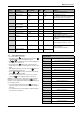
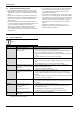
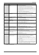
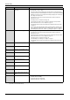
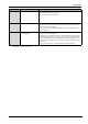
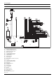
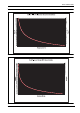
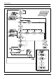
Table Of Contents
- Table of contents
- 1 Key to symbols and safety instructions
- 1.1 Key to symbols
- 1.2 Safety instructions
- 2 FCC rules
- 3 Appliance details
- 4 Installation instructions
- 4.1 Specialized tools
- 4.2 Introduction
- 4.3 Venting
- 4.3.1 Vent options
- 4.3.2 Vent specifications
- Venting specifications
- Condensate drain requirements
- Minimum combustion air and exhaust pipe length
- Maximum combustion air and exhaust pipe length
- Use of elbows
- Calculation example for 3" PVC, CPVC, or ABS venting:
- Calculation example for 4" PP, PVC, CPVC, or ABS venting:
- Calculation example for 2" PVC venting:
- Required direct vent terminal clearances (twin pipe / concentric penetration) for PVC, CPVC, ABS, and PP.
- Required other than direct vent terminal clearances (single pipe penetration) for PVC, CPVC and ABS systems.
- 4.3.3 Vent configuration examples for PP, PVC, CPVC, or ABS systems
- 4.3.4 Vent connections for PP, PVC, CPVC, and ABS systems
- 4.3.5 Connecting the condensate water drain
- 4.3.6 Freeze prevention for PVC, CPVC, and ABS systems
- 4.3.7 Common venting of 2 to 4 units
- 4.3.8 Fan speed adjustment
- 4.4 Combustion air requirements
- 4.5 Proper location for installing your heater
- 4.6 Heater placement and clearances
- 4.7 Hanging appliance on the wall
- 4.8 Mounting installation
- 4.9 Gas piping & connections
- 4.10 Water connections
- 4.11 Water quality
- 4.12 Filling the condensate trap
- 4.13 Domestic hot water recirculation
- 4.14 Space heating applications
- 4.15 Measuring gas pressure
- 5 Electrical connections
- 6 Operation instructions
- 7 Maintenance and service
- 8 Troubleshooting
- 9 Problem solving
- 10 Electrical diagram
- 11 Sensor resistance charts
- 12 Functional scheme
- 13 Interior components diagram
- 14 Protecting the environment
- 15 LIMITED TANKLESS HEATER WARRANTY
- 16 Installer Checklist to be completed by installer upon installation

Problem solving
RTG 199 HE – 6 720 811 617 (2016/01)
47
F9 Gas Control error 1. Check Gas Valve cable harness (connection to gas valve and to ECU)
2. Check Gas Valve (Replace if necessary)
3. Replace ECU (Electronic Control Unit)
F7 Ionization error at standby. 1. Loose connection to the flame ionization rod. Verify that the thinner wire leading
from the control unit is securely connected to the set of electrodes located on the
lower front of the heat exchanger.
2. Flame ionization rod or control unit may be damaged. Contact manufacturer for
further instruction.
FA Gas leakage error, gas valve circuit
not closing properly.
1. Disconnect power supply cord and check wire connections on gas valve and the two
connectors on the control board.
2. Flow water out of a hot water tap above the minimum activation point of 0.5 GPM.
Measure voltage at the gas valve wire plug connection. The voltage should measure
24VDC between the left pair of wires and 24VDC between the right pair of wires
when the unit is operating. If voltage is not proper, contact manufacturer for further
instruction.
3. Gas valve may be defective, contact manufacturer for further instruction.
Display Cause Solution
Table 49
* By installer or service technician only.