
Installation / Operation Instruction Manual
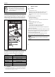
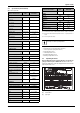
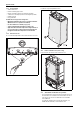
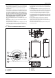
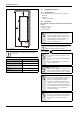
Table Of Contents
- Table of contents
- 1 Key to symbols and safety instructions
- 1.1 Key to symbols
- 1.2 Safety instructions
- 2 FCC rules
- 3 Appliance details
- 4 Installation instructions
- 4.1 Specialized tools
- 4.2 Introduction
- 4.3 Venting
- 4.3.1 Vent options
- 4.3.2 Vent specifications
- Venting specifications
- Condensate drain requirements
- Minimum combustion air and exhaust pipe length
- Maximum combustion air and exhaust pipe length
- Use of elbows
- Calculation example for 3" PVC, CPVC, or ABS venting:
- Calculation example for 4" PP, PVC, CPVC, or ABS venting:
- Calculation example for 2" PVC venting:
- Required direct vent terminal clearances (twin pipe / concentric penetration) for PVC, CPVC, ABS, and PP.
- Required other than direct vent terminal clearances (single pipe penetration) for PVC, CPVC and ABS systems.
- 4.3.3 Vent configuration examples for PP, PVC, CPVC, or ABS systems
- 4.3.4 Vent connections for PP, PVC, CPVC, and ABS systems
- 4.3.5 Connecting the condensate water drain
- 4.3.6 Freeze prevention for PVC, CPVC, and ABS systems
- 4.3.7 Common venting of 2 to 4 units
- 4.3.8 Fan speed adjustment
- 4.4 Combustion air requirements
- 4.5 Proper location for installing your heater
- 4.6 Heater placement and clearances
- 4.7 Hanging appliance on the wall
- 4.8 Mounting installation
- 4.9 Gas piping & connections
- 4.10 Water connections
- 4.11 Water quality
- 4.12 Filling the condensate trap
- 4.13 Domestic hot water recirculation
- 4.14 Space heating applications
- 4.15 Measuring gas pressure
- 5 Electrical connections
- 6 Operation instructions
- 7 Maintenance and service
- 8 Troubleshooting
- 9 Problem solving
- 10 Electrical diagram
- 11 Sensor resistance charts
- 12 Functional scheme
- 13 Interior components diagram
- 14 Protecting the environment
- 15 LIMITED TANKLESS HEATER WARRANTY
- 16 Installer Checklist to be completed by installer upon installation

FCC rules
RTG 199 HE – 6 720 811 617 (2016/01)
6
2 FCC rules
FCC: This device complies with Part 15 of the FCC rules. Operation is
subject to the following two conditions: (1) This device may not cause
harmful interference, and (2) this device must accept any interference
received, including interference that may cause undesired operation.
Fig. 1
The chart below shows the relationship between water temperature and
time until there is a risk of scalding. It can be used as the basis for
determining the safest water temperature for your application.
3Appliance details
3.1 Features
Parts
• Key Pad interface control.
• High power pre-mix compact burner with low NOx emissions.
• Modulating Gas Valve with constant gas:air ratio control.
• Modulating water valve for improved comfort and temperature
control.
High quality materials for long working life
• Copper heat exchanger.
• High efficiency Ceramat Burner.
• Compact space saver: mounts on a wall with a supplied bracket.
Features
• Easily removable one-piece cover.
• On/Off and Temperature control switches.
• Reset button.
• Program button (Selectable temperature default).
• Failure codes for easy diagnostics and repair.
• Real-time diagnostics for troubleshooting/informational purposes.
• Built in freeze prevention.
Note: The freeze prevention kit is designed to provide protection for the
water heater down to approximately 5°F for short term conditions only.
It will not protect the appliance in areas where the temperature is
routinely expected to be below freezing.
- The freeze prevention kit will not protect plumbing outside the
appliance from freezing. Precautions should be taken.
WARNING: Personal Injury from toxic chemicals.
▶ A water heater which will be used to supply potable
water shall not be connected to any heating system
or component(s) previously used with a nonpotable
water heating appliance.
Temperature Time to severe scalding
1)
1) Source: Moritz, A.R. and Henriques, F.C., Jr. (1947). Studies of thermal injury.
II. The relative importance of time and surface temperature in the causation of
cutaneous burns, Am J of Pathol, 23, 695-720.
120 °F (48 °C) longer than 5 minutes
125 °F (51 °C) 1.5 to 2 minutes
130 °F (54 °C) approx. 30 seconds
135 °F (57 °C) approx. 10 seconds
140 °F (60 °C) less than 5 seconds
145 °F (62 °C) less than 3 seconds
150 °F (65 °C) approx. 1.5 seconds
155 °F (68 °C) approx. 1 second
Table 2 Approximate time-temperature relationship until there is a risk
of scalding
Bradford White is constantly improving its products,
therefore specifications are subject to change without
prior notice.