
Installation / Operation Instruction Manual
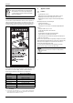
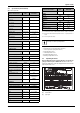
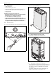
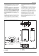
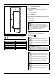
Table Of Contents
- Table of contents
- 1 Key to symbols and safety instructions
- 1.1 Key to symbols
- 1.2 Safety instructions
- 2 FCC rules
- 3 Appliance details
- 4 Installation instructions
- 4.1 Specialized tools
- 4.2 Introduction
- 4.3 Venting
- 4.3.1 Vent options
- 4.3.2 Vent specifications
- Venting specifications
- Condensate drain requirements
- Minimum combustion air and exhaust pipe length
- Maximum combustion air and exhaust pipe length
- Use of elbows
- Calculation example for 3" PVC, CPVC, or ABS venting:
- Calculation example for 4" PP, PVC, CPVC, or ABS venting:
- Calculation example for 2" PVC venting:
- Required direct vent terminal clearances (twin pipe / concentric penetration) for PVC, CPVC, ABS, and PP.
- Required other than direct vent terminal clearances (single pipe penetration) for PVC, CPVC and ABS systems.
- 4.3.3 Vent configuration examples for PP, PVC, CPVC, or ABS systems
- 4.3.4 Vent connections for PP, PVC, CPVC, and ABS systems
- 4.3.5 Connecting the condensate water drain
- 4.3.6 Freeze prevention for PVC, CPVC, and ABS systems
- 4.3.7 Common venting of 2 to 4 units
- 4.3.8 Fan speed adjustment
- 4.4 Combustion air requirements
- 4.5 Proper location for installing your heater
- 4.6 Heater placement and clearances
- 4.7 Hanging appliance on the wall
- 4.8 Mounting installation
- 4.9 Gas piping & connections
- 4.10 Water connections
- 4.11 Water quality
- 4.12 Filling the condensate trap
- 4.13 Domestic hot water recirculation
- 4.14 Space heating applications
- 4.15 Measuring gas pressure
- 5 Electrical connections
- 6 Operation instructions
- 7 Maintenance and service
- 8 Troubleshooting
- 9 Problem solving
- 10 Electrical diagram
- 11 Sensor resistance charts
- 12 Functional scheme
- 13 Interior components diagram
- 14 Protecting the environment
- 15 LIMITED TANKLESS HEATER WARRANTY
- 16 Installer Checklist to be completed by installer upon installation

Appliance details
RTG 199 HE – 6 720 811 617 (2016/01)
7
3.2 Specifications (Technical data)
Approved in US/Canada
Safety devices
• Flame failure device (ionization flame rod sensor)
• Overheat prevention (temperature limiter)
• Inlet temperature sensor
• Outlet temperature sensor
• Back flow temperature sensor
• Exhaust gas temperature sensor
3.3 Unpacking the heater
Before installing the unit, be certain you have the correct heater for
your type of Gas - Propane or Natural Gas. Identification labels are
found on the shipping box, and on the rating plate which is located on the
right side panel of the cover.
Fig. 2 Rating plate
[A] Serial number
[B] Type of gas
Technical characteristics Units RTG 199 H
Capacity
Maximum flow rate at a 45 °F
(25 °C) rise
GPM (l/min) 8.3 (31.4)
Maximum flow rate at a 55 °F
(30.6 °C) rise
GPM (l/min) 6.8 (25.7)
Maximum flow rate at a 75 °F
(41.7 °C) rise
GPM (l/min) 5.0 (18.8)
Maximum flow rate at a 90 °F
(50 °C) rise
GPM (l/min) 4.2 (15.7)
Maximum output BTU/hr (kW) 184,500 (54)
Maximum input BTU/hr (kW) 199,000 (58.3)
Thermal efficiency (Efficiency
in %)
% > 94%
Minimum Input BTU/hr (kW) 19,900 (5.8)
Temperature Control
Selection range °F ( °C) 100 - 140 (38 - 60)
Default temperature °F ( °C) 122 (50)
Stability °F ( °C) 2 ( 1)
Gas Requirement
Gas connection inches ¾ "
Peak load inlet gas pressure
1)
Propane water column 8” - 13”
Natural Gas water column 3.5” - 10.5”
Water
Hot water connection inches ¾ "
Cold water connection inches ¾ "
Minimum water flow
2)
GPM (l/min) 0.5 (1.9)
Minimum recommended water
pressure
PSI (bar) 30 (2.07)
Minimum well pressure PSI 40
Water valve material Polymer (PPS)
(Polypropylene
Sulfide)
Connections: Bottom of heater
Combustion
CO level ppm 290 (measured)
CO
2
level (set from factory) % see table 43
Dimensions
Depth inches (mm) 11 ¼ (286)
Width inches (mm) 17
7
/
8
(452)
Height inches (mm) 30½ (775)
Weight pounds (kg) 74 (33.5)
Gas types
Natural Gas
Table 3
LP Gas
Voltage
Nominal V AC 120
Frequency Hz 60
Amperage
Idle mA 40
Operation A 2.5
Noise db (A) 45 - 65
Water protection
3)
IP X4D
1) To measure Gas Pressure, see Measuring Gas Pressure, chapter 4.15, page 33.
2) Activation varies with inlet water temperatures from 0.5 - 1.6 gallon/minute (1.9
- 6.1 l/m).
3) Protection against water drops.
If appliance is installed at elevations above 2000ft, refer
to chapter 4.3.8 Fan speed adjustment.
Technical characteristics Units RTG 199 H
Table 3