
Installation / Operation Instruction Manual
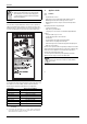
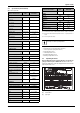
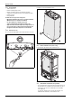
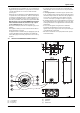
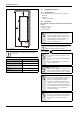
Table Of Contents
- Table of contents
- 1 Key to symbols and safety instructions
- 1.1 Key to symbols
- 1.2 Safety instructions
- 2 FCC rules
- 3 Appliance details
- 4 Installation instructions
- 4.1 Specialized tools
- 4.2 Introduction
- 4.3 Venting
- 4.3.1 Vent options
- 4.3.2 Vent specifications
- Venting specifications
- Condensate drain requirements
- Minimum combustion air and exhaust pipe length
- Maximum combustion air and exhaust pipe length
- Use of elbows
- Calculation example for 3" PVC, CPVC, or ABS venting:
- Calculation example for 4" PP, PVC, CPVC, or ABS venting:
- Calculation example for 2" PVC venting:
- Required direct vent terminal clearances (twin pipe / concentric penetration) for PVC, CPVC, ABS, and PP.
- Required other than direct vent terminal clearances (single pipe penetration) for PVC, CPVC and ABS systems.
- 4.3.3 Vent configuration examples for PP, PVC, CPVC, or ABS systems
- 4.3.4 Vent connections for PP, PVC, CPVC, and ABS systems
- 4.3.5 Connecting the condensate water drain
- 4.3.6 Freeze prevention for PVC, CPVC, and ABS systems
- 4.3.7 Common venting of 2 to 4 units
- 4.3.8 Fan speed adjustment
- 4.4 Combustion air requirements
- 4.5 Proper location for installing your heater
- 4.6 Heater placement and clearances
- 4.7 Hanging appliance on the wall
- 4.8 Mounting installation
- 4.9 Gas piping & connections
- 4.10 Water connections
- 4.11 Water quality
- 4.12 Filling the condensate trap
- 4.13 Domestic hot water recirculation
- 4.14 Space heating applications
- 4.15 Measuring gas pressure
- 5 Electrical connections
- 6 Operation instructions
- 7 Maintenance and service
- 8 Troubleshooting
- 9 Problem solving
- 10 Electrical diagram
- 11 Sensor resistance charts
- 12 Functional scheme
- 13 Interior components diagram
- 14 Protecting the environment
- 15 LIMITED TANKLESS HEATER WARRANTY
- 16 Installer Checklist to be completed by installer upon installation

Appliance details
RTG 199 HE – 6 720 811 617 (2016/01)
8
3.3.1 The box includes
• Tankless water heater
• Bracket for wall hanging the heater
• Exhaust vent adaptor (with 4 screws and gasket provided)
• Combustion air inlet adaptor (with 3 screws and gasket provided)
• Installation manual
• Energy Guide label
The RTG 199 H is not approved or designed for:
• Manufactured (mobile) homes, boats or any mobile installation.
(Modular homes are acceptable for installation).
• Use above 8000 ft A.S.L. altitude (see page 21).
• Outdoor installation without installation of Outdoor kit.
• Applications where inlet water temperature is higher than 140°F
(60°C). A 3-way valve or mixing valve must be installed before
the appliance if inlet water temperature exceeds this limit.
3.3.2 Remove front cover
▶ Loosen the two Phillips head screws located on bottom rear of cover.
Fig. 3 Loosen the two screws
▶ Lift front cover panel upward and remove.
Fig. 4 Remove the front cover
3.3.3 Remove combustion cover (service only)
▶ Open the four clips and remove the combustion cover.
Fig. 5 Remove the combustion cover
3.4 General rules to follow for safe operation
• 1. You must follow these instructions when you install your heater. In
the United States: The installation must conform with local codes or,
in the absence of local codes, the National Fuel Gas Code ANSI
Z223.1/NFPA 54.
In Canada: The Installation must conform with CSA B149.(1,2)
INSTALLATION CODES and /or local installation codes.
6720608917-03.1AL