Technical Service Instruction Intelligent cascading kit Kit components: Cascading cable (2X) 6720811759 /238-51036-00A (2019/07) Approved for the Models: RTG 199HE/ME RTG-K-160/199N/X1 RTG-K-160/199N/X2
Table of contents Table of contents 1 Key to symbols and safety instructions 1 Key to symbols and safety instructions . . . . . . . . . . . . 2 1.1 Key to symbols 1.1 Key to symbols . . . . . . . . . . . . . . . . . . . . . . . . . . . . . 2 Warnings 1.2 Safety instructions. . . . . . . . . . . . . . . . . . . . . . . . . . 3 In warnings, signal words at the beginning of a warning are used to indicate the type and seriousness of the ensuing risk if measures for minimising danger are not taken.
Cascading operation 1.2 Safety instructions H WARNING: Before installation, ▶ Read all instructions. Perform the steps in the indicated sequence. ▶ Failure to comply with these instructions can result in severe, possibly fatal, personal injury as well as damage to property and equipment. H DANGER: Risk of electric shock! ▶ Ensure that only an authorized contractor performs electrical work. ▶ Before performing electrical work, disconnect the power and secure the unit against unintentional reconnection.
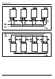
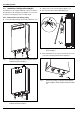
Cascading operation Fig. 1 Cascading setup for models RTG 199HE, RTG 199ME Fig. 2 Cascading setup for models RTG-K-199..1 and RTG-K-160..
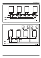
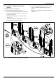
Cascading operation Fig. 3 Cascading setup for models RTG-K-199..2 and RTG-K-160..2 Fig.
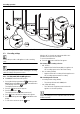
Cascading operation 2.2 Installation of Intelligent Cascading Kit Each appliance comes equipped with two connectors inside for the installation of the intelligent cascading kit. The connectors are labeled 'cascading input' and 'cascading output'. ▶ Lift the front cover to remove from the appliance [1]. ▶ Disconnect the wire from the HMI (display) [2]. 2.2.1 Remove Front cover and ring sealing ▶ Loosen two Phillips head screws located on bottom of cover Fig.
Cascading operation 2.2.2 Connect the cascading cables between the appliances To install the intelligent cascading cables: ▶ Connect all appliances together to form a ring. – Connect units in a row from the first to the last unit and then connect the last unit to the first one to close the ring (fig. 9 and fig. 10). – If one cable is not long enough, connect two or more cables in a row. – Use the holes at the bottom of the appliance to guide the cables to/from the appliance interior. Fig.
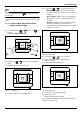
Cascading operation Fig. 10 2.3 Example of installation for: RTG-K-199N/X1, RTG-K-160N/X1, RTG-K-199N/X2 and RTG-K-160N/X2 Cascading settings Perform this procedure on all appliances in the cascading setup. This step can only be performed after installing the cascading cables according to the previous section. 2.3.1 For RTG 199HE, RTG 199ME appliances ▶ Push ON/OFF switch to the OFF position. 1. Press and hold the program button P and then press the ON/OFF button to the ON position.
Cascading operation Selection is done pressing the starts flashing. P button until the display The appliance is now programmed to operate in the cascading mode. 2.3.2 For RTG-K-199N/X1, RTG-K-160N/X1, RTG-K199N/X2 and RTG-K-160N/X2 ▶ Press simultaneously + and buttons, and seconds. Display shows P4 (Information). P ▶ Press buttons + or to scroll through the options. – MA (Primary) - Appliance defined as Primary. Only one appliance in the cascading system can be defined as Primary.
Cascading operation 2.4 Primary/Secondary identification The primary appliance is identified by the following symbol; 2.5.3 Error handling When one appliance in the cascading system is locked, due to an error code, all actions are sent to the next appliance. If the appliance is a Primary, it will request to the next appliance to be the primary.
Cascading operation 6720811759 (2019/07) 11
Bosch Thermotechnik GmbH Sophienstrasse 30-32 D-35576 Wetzlar www.