Solar Water Heater With Electric Backup Solar Saver ® Heaters SERVICE MANUAL Troubleshooting Guide and Instructions for Service (To be performed ONLY by qualified service providers) Models Covered by This Manual: S-SW2-60R6DS S-SW2-75R6DS S-SW2-115R6DS Manual 238-47297-00A Save this manual for future reference
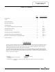
Solar Water Heater With Electric Backup Table of Contents Page Service Procedure Introduction ………………………………………………………………………. 2 Tools……………………………………………………………………………… 2 General Information ……………………………………………………………… 3 --- Sequence of Operation …………………………………………………………… 5 --- Troubleshooting ……………………………………………………………….…. 6 --- Line Voltage and High Limit (ECO) Testing…………………………………..… 8 RE-I Heating Element Testing ……………...................................................................
GENERAL INFORMATION Commonly Used Formulas Single Phase Amps = Watts Volts Example 4500W/240V = 18.75A Watts = Amps x Volts Example 18.75A x 240V = 4500W Ohms = Volts 2 Watts Example (240V) / 4500W = 12.
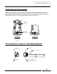
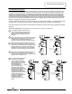
GENERAL INFORMATION Surface Mounted Thermostats Surface mounted thermostats are mounted into a bracket which holds the thermostat against the side of the tank. Surface mounted thermostats respond to tank surface temperatures to sense a call for heat, set point temperature settings and high limit (ECO) activation. It is important that the entire back surface of the thermostat is in full contact or flush with the tank. Improperly mounted thermostat will lead to improper heater operation.
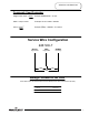
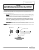
SEQUENCE OF OPERATION Non-Simultaneous Operation Non-Simultaneous Mode: Allows only one heating element to operate at a time. For example, when the tank is cold, the upper element is energized first, heating the top of the tank. Only when the upper thermostat is satisfied, the upper element is de-energized and power is directed to the lower thermostat, energizing the lower element and heating the bottom portion of the tank until the lower thermostat is satisfied.
TROUBLESHOOTING NOTICE This Service Manual is for servicing the solar water heater. If other components of an installed system requires service, those questions should be directed to the installer or the specific component manufacturer. Most common cause for improper electric backup operation can be linked to heating element failure.
TROUBLESHOOTING Quick Step Plan to Hot Water 1. TURN OFF power to water heater and solar controller. Check all wire connections to insure they are tight and corrosion free. 2. Turn power “ON” and determine that service voltage is present and the high limit (ECO) has not actuated (see procedure on page 8). WARNING High voltage exposure. Use caution when making voltage checks to avoid personal injury. NOTICE This Service Manual is for servicing the solar water heater.
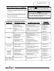
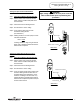
SERVICE PROCEDURE RE-I Line Voltage & High Limit (ECO) Testing Line Voltage Testing WARNING High voltage exposure. Use caution when making voltage checks to avoid personal injury. 1. Turn “OFF” power to water heater. 2. Remove access cover(s) from front of water heater. Remove insulation and plastic cover from thermostat. ECO reset button 3. Set multi-meter to volts AC. 4. Turn power “ON” to water heater. 5. Check voltage across terminals L1 & L3 of upper thermostat (see illustration 2).
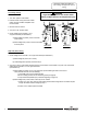
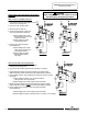
SERVICE PROCEDURE RE-II Heating Element Testing Testing For Open Or Burned Out Element. Step 1. TURN OFF POWER TO WATER HEATER. Step 2. Remove access covers from front of water heater. Remove insulation and plastic cover from thermostat. WARNING High voltage exposure. Be sure power is turned OFF to water heater prior to performing this procedure. Step 3. Disconnect wires from heating element. Step 4. Set multi-meter to “ohms” setting. Step 5.
SERVICE PROCEDURE RE-III Thermostat Testing Double Element, Non-Simultaneous, Single Phase Operation. WARNING High voltage exposure. Use caution to avoid personal injury during this procedure. Water In Tank Is Cold With Power ON. 1. This procedure assumes line voltage, ECO and elements are in working order. 2. Turn power “ON” to water heater. 3. Set multi-meter to “Volts AC”. 4. Check across terminals L4 and T2 of upper thermostat (see illustration 6). A) Rated voltage NOT present, Recheck ECO.
SERVICE PROCEDURE RE-III Thermostat Testing Double Element, Non-Simultaneous, Single Phase Operation (continued). WARNING High voltage exposure. Use caution to avoid personal injury during this procedure. Not Enough Hot Water (continued). 7. Check voltage across terminal L4 of upper thermostat and terminal 1 of lower thermostat (see illustration 9). A) Rated voltage NOT present, - check wire connection between thermostats. B) Rated voltage IS present, okay, go to step 8. 8.
SERVICE PROCEDURE RE-IV Thermostat Removal and Replacement Thermostat Removal WARNING High voltage exposure. Be sure power is “OFF” when performing this procedure. 1. Turn power “OFF” To water heater. 2. Remove access cover and insulation. 3. Remove plastic thermostat protector from thermostat. 4. Disconnect wires from thermostat terminals. It may be necessary to label wires for proper re-connection to new thermostat. 5. Note thermostat temperature setting for proper setting of new thermostat. 6.
SERVICE PROCEDURE RE-V Heating Element Removal and Replacement WARNING High voltage exposure. Be sure power is “OFF” when performing this procedure. Heating Element Removal 1. Turn power “OFF” To water heater. 2. Turn off cold water supply to heater. Connect hose to drain spigot of water heater and route to an open drain. Open a nearby hot water faucet to vent heater for draining. Open drain spigot of water heater and allow heater to drain to a point below the elements. 3.
SERVICE PROCEDURE RE-VI Dip Tube and Anode Inspection and Replacement Dip Tube Inspection and Replacement WARNING Heater components and stored water may be HOT when performing the following steps in this procedure. Take necessary precaution to prevent personal injury. Step 1. Turn power “OFF” to water heater. Step 2. Turn off cold water supply to heater. Connect hose to drain spigot of water heater and route to an open drain. Open a nearby hot water faucet to vent heater for draining.
Generic Parts List 1. Integrated Mixing Device 2. Hex Head Anode 3. Junction Box Cover 4. Cover Conduit/Ground 5. ¾" Plug 6. Hot Water Outlet/Anode 7. Cold Water Inlet Dip Tube 8. Access Cover 9. Thermostat Protector (Large) 10. Heating Element 11. Thermostat Mounting Bracket 12. Thermostat w/High Limit (89T33) 13. Element Gasket 14. T&P Relief Valve 15. Lower Thermostat Protector (Small) 16. Thermostat (59T) 17. Brass Drain Valve 18.
Email parts@bradfordwhite.com techserv@bradfordwhite.com www.bradfordwhite.