The Bradford White R (To be performed ONLY by qualified service providers) R U130T*FRN U130S*FRN U140T*FRN U1403T*FRN U1403S*FRN U1404T*FRN U1503*FRN U150L*FRN U1504S*FRN U430T*FRN U440T*FRN U4403S*FRN U4503*FRN U1XR403S*FRN (*) Denotes Warranty Years.
The Bradford White R Ultra Low NOx Gas Water Heaters Page Service Procedure Introduction 3 --- Gas Control Troubleshooting Chart 5 --- Tools Required for Service 4 --- Burner and Inner Door Gasket Removal, Inspection, Replacement and Installation 7 ED-I Thermopile Testing and Replacement 10 ED-II Pilot Assembly Inspection, Cleaning and Replacement 12 ED-III Igniter and Electrode Testing and Replacement 13 ED-IV Gas Control Replacement Thermal Well and Chamber Door Sensor Testing an
INTRODUCTION The Bradford White ECO-DEFENDER Safety System The Bradford White ECO-DEFENDER Safety System was designed to resist the ignition of flammable vapors that can occur outside of the water heater. In addition, the ECO-DEFENDER Safety System is designed to meet the stringent NOx emissions standards required in the South Coast Air Quality Management District (SCAQMD) Rule 1121. Use and installation are nearly identical to previous versions of atmospherically fired and vented water heaters.
How to Use This Manual It is intended for this manual to be used by qualified service personal for the primary purpose of troubleshooting and repair of the Bradford White ECO-DEFENDER Series of water heaters. The Honeywell WV8860Q Gas Control will display error codes in the event of abnormal operation. Error codes are listed in the troubleshooting chart beginning on page 5 of this service manual.
Gas Control Troubleshooting Observe red LED indicator on gas control. Error flash codes are displayed with a three second pause before repeating. Check and repair the system as noted in the troubleshooting table below. Red LED Indicator LED Status Control Status Gas valve is operating normally. Pilot flame None (LED not on may not be present. or flashing) Check for pilot flame through sight glass and light if necessary.
Gas Control Troubleshooting LED Status Control Status Probable Cause Service Procedure 1. Damage to the Five flashes thermowell wire. and three Thermostat well fault. 2. Thermowell See page 14. second sensor resistance pause. out of range. Chamber door 1. Chamber door Six flashes temperature sensor out temperature sensor and three of specification. out of calibration. See page 18. second Possible electrical 2. Possible pause. short. electrical short. 1.Turn gas control knob Seven flashes 1.
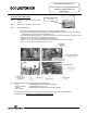
SERVICE PROCEDURE ED-I Burner and Inner Door/Gasket Removal, Inspection, Replacement and Reinstallation Inner Door Removal Procedure Step 1. Rotate the gas control knob to the “OFF” position. Step 2. Remove outer jacket burner access door Step 3. Inner Door Removal. Gas Control Knob Shown In “OFF” Position a) Disconnect chamber door temperature sensor wire harness from the gas valve. b) Disconnect resettable thermal switch white wire lead (leading from gas valve).
SERVICE PROCEDURE ED-I Burner and Inner Door/Gasket Removal, Inspection, Replacement and Reinstallation Inner Door Gasket Replacement Procedure. WARNING If the information in these instructions is not followed exactly, a fire or explosion may result causing property damage, personal injury or death. Step 5. After inspection of inner door as noted in step 4, completely remove gasket and adhesive residue from burner and left side inner doors as needed. Step 6.
SERVICE PROCEDURE ED-I Burner and Inner Door/Gasket Removal, Inspection, Replacement and Reinstallation Position Thermopile Wire, Pilot Tube and Igniter Wire Step 10. Firmly place right side inner door flange against the burner door flange and secure with two ¼” drive screws from step 3e. DO NOT OVER TIGHTEN SCREWS. Step 11. Align right side inner door to combustion chamber and verify the fastener holes of the combustion chamber are aligned with the right side inner door slotted opening.
SERVICE PROCEDURE ED-II Thermopile Testing and Replacement CLOSED CIRCUIT THERMOPILE TESTING (Honeywell Control) Step 1. Closed circuit testing is the preferred method for testing thermopile. Following the lighting instruction label on the heater, proceed to light the pilot and allow to operate for three minutes. If the pilot will not stay lit, hold the pilot button (rotate the gas control knob to the pilot position, push and hold in) during this test Step 2.
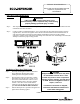
SERVICE PROCEDURE ED-II Thermopile Testing and Replacement THERMOPILE REPLACEMENT Step 1. Turn off gas supply to water heater. Rotate gas control knob to the “OFF” position. Gas Control Knob Shown In “OFF” Position Step 2. Remove outer jacket door. Step 3. Remove right side inner door and burner door per SERVICE PROCEDURE RG-I, steps 3a through 3g. Step 4 Disconnect the red thermopile wire from the wire harness and the white thermopile wire from the resettable thermal switch.
SERVICE PROCEDURE ED-III Pilot Assembly Inspection, Cleaning and Replacement PILOT/ELECTRODE ASSEMBLY INSPECTION, CLEANING AND REPLACEMENT Gas Control Knob Shown In “OFF” Position Step 1. Turn off gas supply to water heater. Rotate gas control knob to the “OFF” position. Step 2. Remove outer jacket door. Step 3. Remove burner and right side of inner door per SERVICE PROCEDURE ED-I, steps 3a through 3g. Step 4. Remove burner assembly from combustion chamber. Step 5.
SERVICE PROCEDURE ED-IV Igniter and Electrode Testing and Replacement IGNITER, ELECTRODE TESTING AND REPLACEMENT With the pilot not in operation (no pilot flame) you can check the igniter and electrode circuit by viewing pilot thru the sight glass located on the inner door and observing the spark action. Step 1. Remove outer jacket door. Step 2. Repeatedly depress the igniter button while viewing the pilot thru the sight glass. If a spark is present, the circuit is OK.
SERVICE PROCEDURE ED-V Gas Control Replacement Thermal Well and Chamber Door Sensor Testing and Replacement Thermal Well Testing Disconnect thermal well wire harness If Control has gone into lockout due to excessive tank temperature (four flash, 3 second pause) reset control by rotating gas control knob to “OFF” position. Then follow lighting instructions and return gas control knob to desired setpoint. Observe heater operation.
SERVICE PROCEDURE ED-V Gas Control Replacement Thermal Well and Chamber Door Sensor Testing and Replacement WARNING Stored water may be HOT when performing the following steps in this procedure. Take necessary precaution to prevent personal injury. Determine Water Temperature Inside Tank Note: It is important to understand once the resistance for the thermal well is determined from page 14, water flow through the heater should not occur.
SERVICE PROCEDURE ED-V Gas Control Replacement Thermal Well and Chamber Door Sensor Testing and Replacement Gas Control & Thermal Well Removal From Water Heater Gas Control Step 1. Turn the gas control knob to the “OFF” position. Step 2. Drain heater to a point below the gas control level. Step 3. Turn off gas supply to water heater and disconnect gas piping from gas control. Step 4. Disconnect wire harnesses and burner assembly from gas control. Step 5.
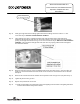
SERVICE PROCEDURE ED-V Gas Control Replacement Thermal Well and Chamber Door Sensor Testing and Replacement Gas Control Assembly to Thermal Well Step 1. Install threaded end of thermal well into tank. Be sure thermal well flange is positioned as shown in photo 3 for proper control alignment. Step 2. Route wire leads back into relief opening. (see photo 3). Step 3. Align slots located on thermal well flange with tabs located on back of gas control (see photos 3 & 4).
SERVICE PROCEDURE ED-V Gas Control Replacement Thermal Well and Chamber Door Sensor Testing and Replacement CHAMBER SENSOR TESTING Step 1. Turn the gas control knob to the “OFF” position Step 2. Disconnect the chamber sensor wire harness from the gas valve. Step 3. Remove the chamber door temperature sensor from the right side inner door (Phillips screw driver). Step 4. Make sure that the ring terminal of the chamber door temperature sensor is not touching any surface.
SERVICE PROCEDURE ED-VI Burner Operation Inspection, Cleaning and Replacement MAIN BURNER: Inspection, Cleaning and Replacement At periodic intervals (not more then 6 months) a visual inspection should be made of the main burner for proper operation and to insure no debris is accumulating. Main burner should light smoothly from pilot and burn with a blue flame with a minimum of yellow tips. After 5 minutes of operation the burner screen will become radiant and the flame will soften and turn orange.
SERVICE PROCEDURE ED-VI Burner Operation Inspection, Cleaning and Replacement BURNER CLEANING (Cont.) Step 5. Disconnect (unscrew) manifold mount from feed line. Use a stiff brush, compressed air and/or shop vacuum to remove any debris build up from the manifold mount. Step 6. Remove main burner orifice from feed line (3/8" wrench). Inspect and clean if necessary Step 7. Remove pilot assembly, refer to SERVICE PROCEDURE ED-III for cleaning and inspection. Step 8. Reassemble burner. Step 9.
SERVICE PROCEDURE ED-VII Resettable Thermal Switch Testing and Replacement RESETTABLE THERMAL SWITCH CONTINUITY TESTING Step 1. Remove outer jacket door. Step 2. Disconnect white wire leads from resettable thermal switch. Step 3. Using a multimeter capable of measuring continuity (Ohms), place one probe of meter on one of the brass connection tabs of the resettable thermal switch, and the remaining probe on the other connection tab. Step 4.
SERVICE PROCEDURE ED-VII Resettable Thermal Switch Testing and Replacement RESETTABLE THERMAL SWITCH REPLACEMENT Step 1. Rotate gas control knob to the “OFF” position. Gas Control Knob Shown In “OFF” Position Step 2. Remove outer jacket door. Step 3. Disconnect wire leads from resettable thermal switch. Step 4. Remove (2) ¼” hex drive screws from the manifold mount. Step 5. Bend the flexible feed line so the resettable thermal switch is easily accessible. Step 6.
SERVICE PROCEDURE ED-VIII ScreenLok Flame Arrestor Cleaning ScreenLok Flame Arrestor Cleaning Step 1. Rotate gas control knob to the “OFF” position. Gas Control Knob Shown In “OFF” Position Step 2. Remove outer jacket door. Step 3. Remove burner and inner door per SERVICE PROCEDURE ED-I, step 3a through 3g. Step 4. Clean ScreenLok Flame Arrestor using stiff brush, compressed air and/or shop vacuum to remove any scale or other debris accumulation.
SERVICE PROCEDURE ED-IX Dip Tube and Anode Inspection and Replacement DIP TUBE INSPECTION AND REPLACEMENT WARNING Water Heater components and stored water may be HOT when performing the following steps in this procedure. Take necessary precaution to prevent personal injury. Step 1. Rotate gas control knob to the “OFF” position. Gas Control Knob Shown In “OFF” Position Step 2. Turn off cold water supply to water heater. Connect hose to drain spigot of water heater and route to an open drain.
SERVICE PROCEDURE ED-IX Dip Tube and Anode Inspection and Replacement ANODE INSPECTION AND REPLACEMENT WARNING Heater components and stored water may be HOT when performing the following steps in this procedure. Take necessary precaution to prevent personal injury. Step 1. Turn off water supply to water heater. Rotate gas control knob to the “OFF” position. Gas Control Knob Shown In “OFF” Position Step 2. Turn off cold water supply to heater.
1 2 3 4 5 6 7 8 9 10 11 12 13 14 15 16 17 18 19 20 21 22 23 24 25 26 27 28 29 30 31 32 Flue Baffle Hot Water Outlet/Anode Cold Water Inlet Tube T&P Relief Valve Thermal Well Brass Drain Valve Gas Valve Main Burner Orifice Heat Trap Inlet Heat Trap Outlet Outer Door Draft Diverter Complete Burner Assembly RN Burner and Door Flexible Gas Feed Line Pilot Assembly Page 26 26 Screw #8-18 x ½ Hex Washer Head Resettable Thermal Switch Screw #6-20 x 3/8 PHCR Screw #8-18 x ¾ Hex Washer Head Manifold Mount Compl
Email parts@bradfordwhite.com techserv@bradfordwhite.com www.bradfordwhite.