
Installation manual

SS-2N/AST/STD, SS-2N/AST/WH Installation
8 10/24/11 Bradley Corporation • 215-1498 Rev. F; ECM 11-08-011
4a
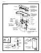
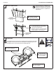
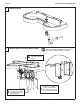
Connect the Supply — Hot and Cold Supply
4b
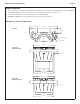
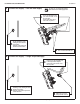
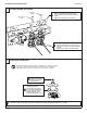
Connect the Supply — Single Tempered Supply
The letter “H” on the Navigator Mixing
Valve indicates hot water supply inlet.
Loosen but do not remove
the two mounting screws
holding the valve bracket
to the frame.
Slide the valve bracket up
and lift it from the frame.
A
Connect one end of each
hose to the Navigator valve
(one on the hot side, one on
the cold side).
Connect the other swivel
end to the stop valves.
C
Attach the stops to the hot
and cold water wall stub-outs.
B
Loosen but do not remove the two
mounting screws holding the valve
bracket to the frame.
Slide the valve bracket up and lift
it from the frame.
A
Connect one end of flexible hose
to the tempered line adapter.
Connect the other swivel end to
the stop valve.
C
Attach the stop to the
tempered wall stub-out.
B