
Installation manual

SS-3N/AST/STD, SS-3N/AST/WH Installation
8 12/11/07 Bradley Corporation • 215-1494 Rev. E; ECN 07-814
4a
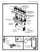
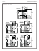
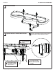
Connect the Supply — Hot and Cold Supply
The letter “H” on the Vernatherm™ Mixing
Valve indicates hot water supply inlet.
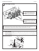
4b
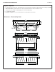
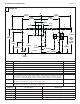
Connect the Supply — Single Tempered Supply
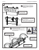
Loosen but do not remove
the two mounting screws
holding the valve bracket
to the frame.
Slide the valve bracket up
and lift it from the frame.
A
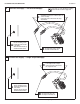
Loosen but do not remove
the two mounting screws
holding the valve bracket
to the frame.
Slide the valve bracket up
and lift it from the frame.
A
Connect one end of flexible hose
to the tempered line adapter.
Connect the other swivel end to
the stop/check valve.
C
Using a thread sealer, thread
the stop/check valve onto
the tempered wall stub-out.
B
Connect one end of each hose to the
Vernatherm™ valve (one on the hot side, one
on the cold side).
Connect the other swivel end to the stop/
check valves.
C
Using a thread sealer, thread
the stop/check valves onto the
hot and cold wall stub-outs.
B