
Specifications


Classic Circular 36"/54" Washfountain with Air Valve Control
Installation Instructions WF2605, WF2608 Terrazzo – WF2705, WF2708 Stainless Steel
13Bradley Corporation • 215-1521 Rev. D; EN 06-915B 4/6/2007
Installation Instructions continued . . .
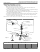
Step 5b: Installing Supplies with Optional Soap Dispenser for B/H drain units
1. Install hemmed end (not sharp end) of support tube with gasket onto bowl as shown in Figure 9
on page 14.
2. Connect 1/2" supply tubing to sprayhead as shown in Figure 7 on page 11. Follow the
procedures below when installing 1/2" tubing into sprayhead to ensure that you achieve a
leakproof seal.
• Using a sharp knife, cut tubing squarely and remove any burrs. DO NOT pinch or crush end of
tubing.
• Loosen nut on fitting. Moisten end of tube and push into fitting until it is firmly seated. Tighten
nut to secure tube to fitting (make sure nut is securely tightened).
• If connector leaks, reseat tubing according to above procedure. If leaking persists, replace male
connector, or call your Bradley representative for assistance.
3. Place sprayhead with 1/2" tubing onto support tube as shown in Figure 9. Run tubing down
through support tube.
4. Place air module assembly on top of sprayhead.
5. Run 1/8" tubing through the support tube and down into the pedestal.
6. Insert the 1-1/2" vent pipe (supplied by installer, see page 4 for length) through the air module,
sprayhead, and support tube.
7. Connect to the vented trap provided.
8a. FOR UNITS WITH SOAP OPTION: Place the spacer, soap dispenser and cover in position on
top of air module (see Figure 9). Slide soap tie bar over 1-1/2" vent pipe 1/2" below top of soap
dispenser cover and secure with the two cap screws included with the tie bar. Slide the dispenser
cover over 1-1/2" vent pipe and secure with the two cap screws included with the tie bar.
8b. FOR UNITS WITHOUT SOAP OPTION: Slide module tie bar over 1-1/2" vent pipe, 1/2"
below top of air module cover and secure with set screws. Slide the dispenser cover over
1-1/2" vent pipe and secure with the two cap screws included with the tie bar.
9. Connect vent pipe to vent through ceiling with pipe union.
10. Continue installation with Step 6 on page 15.