Cable Management Solution User’s Manual
Copyright and Trademarks Copyright and Trademarks This manual is proprietary to Brady Worldwide, Inc. (hereafter "Brady"), and may be revised from time to time without notice. Brady disclaims any understanding to provide you with such revisions, if any. This manual is copyrighted with all rights reserved. No portion of this manual may be copied or reproduced by any means without the prior written consent of Brady.
Preface Preface NetDoc™ is a web-enabled database package that helps you better document and manage your complete network. With this Cable Management Solution (CMS), you can document horizontal and backbone cables, hardware, assets, pathways, locations, users, and much more. Information from NetDoc™ can also be seamlessly exported into Brady LABELMARKTM software to assist you in easily labeling your entire infrastructure.
Preface This page is intentionally left blank.
Contents Copyright and Trademarks ........................................................................................ii Preface ........................................................................................................................iii Infrastructure Setup and Documentation .............................................................. iii Documentation ......................................................................................................
TOOLS MENU.................................................................................................. 1-34 Export to Brady LABELMARK™................................................................ 1-34 Export to LABELMARK™ (quick) .............................................................. 1-39 Import Tester Data..................................................................................... 1-40 User Defined Fields ............................................................................
Grounding ...................................................................................................... 1-114 Adding Busbars ....................................................................................... 1-114 Adding a Conductor ................................................................................ 1-115 Conductor Pathways Used...................................................................... 1-117 Firestops ....................................................................
Chapter 1 - Exploring NetDoc™ Exploring the Application The NetDoc™ interface is comprised of several sections. To keep everything uniform, the look of the software remains the same throughout the application. The interface layout contains a navigator, spreadsheet view area, detail section, locator area, and helpful links. The NetDoc™ environment was designed to satisfy all of your documentation needs, while remaining easy to use and navigate.
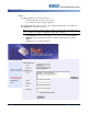
Exploring the Application Links The Main Page links are located in two places: • Under the “Welcome” message on the left side • In a column of five menus along the right side. The left side displays the name of the user who logged in and the name of the database to which NetDoc™ is currently connected. Note: The user name only appears in the software if security is turned on and is used. If a user’s security is not turned on, individual’s names will not display.
Exploring the Application Menus The Main Menu, on the right side of the Main Page, consists of five submenus. See “Working with Menus” on page 1-30 for details. Following is a brief description of each menu link: NETDOC menu: Launch Application — Launches the main NetDoc area where you document network components. Help — Opens online help feature. About — Provides NetDoc version number.
Exploring the Application Application Areas When you launch the application, the data is divided into four major sections. The following information describes each of these secitons. Workspace The NetDoc™ workspace is divided into four major sections: 1 Navigation Tree: A navigation feature similar to Windows Explorer that lets you navigate quickly to any area in the database. See “Navigation Tree” on page 1-5 for details.
Exploring the Application Navigation Tree The Navigation Tree shows the physical and geographical layout of your infrastructure and lets you move around quickly and efficiently. No matter how complex your infrastructure, you can go anywhere within it from the Navigation Tree. Note: The Navigation Tree functions similarly to Microsoft’s Windows Explorer.
Exploring the Application Hierarchy Descriptions When you select a level in the Navigation tree, the selection is highlighted and the details for that selection display in the other sections of the Workspace. Also, when you hover your cursor over any item on the tree, a floating box opens with the name and type of infrastructure item. If the item is a Faceplate, the box will also include the ports connected with it. The following illustrates the standard hierarchy for the Navigation Tree.
Exploring the Application Location Info The Location Info section is located on the left side of the workspace under the Navigation Tree. Depending on where you are in the Navigation Tree, the Location Info section displays the Company, Campus, Building, Floor and/or Space for your current (highlighted) selection (see “Hierarchy Descriptions ” on page 1-6 for more detail.
Exploring the Application List View The List View is located in the upper right pane of the workspace and resembles a spreadsheet. The records displayed are based on your location in the Navigation Tree. Note: Information displayed changes depending on the category selected and your location on the Navigation Tree (e.g., if you move to a higher level on the tree, details for that level and space will display in the List View).
Exploring the Application Getting around the List View • Choose a category from the drop-down list in the List View to display the records in the selected category for the current tree location. The drop-down list includes the following infrastructure categories: • Click any item in the table to display detailed information for that entry in the Detail View. • Click the button in the first column of the List View pane to display detailed view for that component.
Exploring the Application List View User Buttons Button Description Copy lets you duplicate the item being copied. This provides an easier way of building specific network components. Add lets you create a new record in whichever area you have selected. Delete lets you delete a record. Move lets you quickly choose a new location in the Navigation Tree in which to move the selected item(s). For example, you can move an entire department from one place to another.
Exploring the Application Detail View When an item is selected from the List View table, the Detail View displays the details documented for the selected record. You can change to a different record by selecting a different row in the table, either by scrolling through the records using the arrow keys or by clicking on a record with your mouse. The display for the Detail View is linked to the selected item in the List View.
Using the Application Tools Using the Application Tools Notes and Attachments Notes let you enhance your documentation needs by relaying information to others, saving specific notes for future use and providing an aid for all users in recalling necessary information. Notes also help you better document your network by providing additional space for valuable information. Attachments can be added at any level as a link to an outside file to better enhance your documentation needs.
Using the Application Tools Notes In NetDoc™, notes can be added at any level of your infrastructure throughout the application. The Notes capability is located on the Notes and Attachments tab in the Detail pane. Note: Depending on your selection, you can also attach notes down to the port level of a piece of hardware/asset and to the strand level of a backbone cable directly from the tab windows in the Detail pane. To add Notes on the Notes and Attachments tab: 1. Click the Notes and Attachments tab. 2.
Using the Application Tools Adding Notes at Port or Strand Level To add notes at the Port or Strand Level: Within these tabs, to the far right of each row will be a Notes column. 1. On the Port/Position or Pair/Strand Details tab, click the Notes button on the right of the selected item. 2. In the Notes field, type your notes and comments into the Note dialog box. 3. Click OK (or click Cancel to cancel the note).
Using the Application Tools Attachments The attachment capability is located throughout the application and at every level of your infrastructure navigation tree. The Attachments section is located in the Detail View on the Notes and Attachments tab. Note: You must have a viewer installed for the selected file type on your client machine to view the attachment in an HTML formatted window. You can use attachments to better illustrate needed information about your network.
Using the Application Tools To view an Attachment: 1. Locate your attachment in NetDoc™. 2. Click View next to your attachment. The file will launch in an HTML-formatted window. Note: You must have a viewer installed for the selected file type on your client machine to view the attachment in an HTML formatted window. 3. Close the HTML window when you are finished viewing the file. To delete an Attachment: 1. Locate your attachment in NetDoc™. 2. Click Delete next to your attachment. 3.
Using the Application Tools Multi-View / Multi-Task NetDoc™ allows multi-viewing and multi-tasking while navigating throughout the application. You can open detail views of multiple items for use during your working session. Pop-up windows are an essential part of NetDoc™ and enhance your working capability. You can minimize any pop-up window for later use and continue working. You can then restore the pop-up window without having to return to where the screen was originally opened.
Using the Application Tools Search Records shown in the List View table of the NetDoc™ window can be searched across multiple fields, using whatever search text is entered. To use the search function: Note: From the search window, you can change the category and perform another search. However, to change the level on the Navigation Tree, you must close the search results window and highlight the new location on the Navigation Tree. 1.
Using the Application Tools Quick Set/Quick Insert Shortcut buttons exist throughout the application. These shortcuts let you quickly choose a location for a component or, insert a component in the Cable Path. Note: When you click on the Quick Set or Quick Insert button, the Navigation Tree turns blue. You can choose a location from which to incorporate the information for that location into the current selection’s detail record.
Using the Application Tools Copy The Copy capability is available throughout the application and is always located in the List View pane. Copy allows a selected item to be completely copied into the Detail View area where you can then modify any of the information. This is helpful for creating new components that closely resemble already-built components. If properly used, Copy will minimize typing time and user errors.
Using the Application Tools Circuit and Pathway Trace Tool This tool lets you view all of the components of an individual circuit or pathway in both text and graphic format. Tracing is helpful in identifying the source of a problem in the network or in viewing a circuit or path in diagram form. A trace can be performed from a port on an asset or hardware component, strand of a backbone cable, horizontal cable, and pathway screen.
Using the Application Tools To access the Trace tool: 1. From the Main Page, click Launch Application. 2. In the List View, highlight the trace point component. 3. In the Detail View for the selected component, click the appropriate tab. 4. Choose the component you want to view. 5. Click the box in the Trace column for the component you want to view. A separate window opens displaying the details in both table and graphic formats.
Using the Application Tools Trace Table Elements Use these procedures to work with the Table elements in the Trace window. Show/Hide Table To hide the table or diagram: 1. From the Trace window, click the Hide Table or Hide Diagram link. When hidden, the link will change to Show Table or Show Diagram. 2. Click again to re-display the element. Invert Table To show components listed in reverse order: 1. From the Trace window, click Invert Table.
Using the Application Tools Trace Diagram Elements Use these procedures to work with the Diagram elements in the Trace window. Show/Hide Diagram To hide the table or diagram: 1. From the Trace window, click the Hide Table or Hide Diagram link. When hidden, the link will change to Show Table or Show Diagram. 2. Click again to re-display the element. Arrange the Diagram The default arrangement for the graphic diagram is a straight line from left to right.
Using the Application Tools View Component Detail From the Trace window, you can display the Detail View information for any component shown in this window. To view a component's Details View information: 1. Click the component ID link in the box containing the illustration. 2. A pop-up window will display the Detail View for that item. The Detail View also contains tabs that let you quickly filter through all of the component details.
Using the Application Tools Change the Trace Point You can change the trace point from within the diagram by choosing another port, pair/strand, or pathway for any component. This will change the information on the table and the diagram. To change a trace point: 1. In any of the illustration boxes, click the ports, pairs/strands, or pathways link for that item. A menu of all items connected to that component displays, including those both used and available. 2.
Using the Application Tools Visual Connector The Visual Connector tool lets you visually connect all of your cross connections using a graphical representation of your hardware and hardware assets. With this tool, you select your assets and use the drag & drop capability to quickly connect to the ports from one asset to another. To use the visual connector: 1. In the List View area, click Visual Connector. 2. Select an asset from the drop-down list.
Using the Application Tools 5. To connect the port(s), drag your cursor from a port on one asset and drop it on the port of another asset. The connection between ports will display in the Detail area. If you cannot connect an asset a message will display. 6. To delete a connection, click on the connecting line between the two ports. At the prompt asking if you want to delete the connection, click OK.
Using the Application Tools Add Asset from Visual Connector Screen If you need to create another asset for your connections, you can easily do that without leaving the Visual Connector screen. To add an asset: 1. Select the type you want to add (asset, termination hardware, horizontal kink or backbone). 2. Click Create Asset or Create Backbone. The appropriate Detail window will display in a separate pop-up window. 3. Enter the information for that asset type.
Working with Menus Working with Menus In addition to a link to the application, the NetDoc™ main page contains links to a variety of tools, wizards, Set up information and other application features. The following includes information and procedures on how to use the features for each of these links.
Working with Menus REPORTS MENU The Report Creator feature, designed to reinforce and enhance the documentation capabilities in NetDoc™, lets you print comprehensive reports about your infrastructure. The Report Creator link is located on the Main Page and can be used to access all built-in NetDoc™ reporting capability. Report Creator The following reports can be viewed and printed using the Report Creator: • Asset Report: Details Accounting Information and Attributes of the asset.
Working with Menus Generate a Report Each report has selection criteria specific to that report. Example: The Horizontal Link Cable Report window contains radio buttons to select All Criteria, By Date Tested, By HL Type, and By Location. If you select: - All: the report includes all Horizontal Links stored in NetDoc™. - Filter By Date Tested: the report includes HLs that were tested within the date range you specified in the From and To fields.
Working with Menus To generate a report from Report Creator: 1. On the Main Page, click Report Creator. The Report Creator window displays the available reports. 2. Click the link or name of the report you want to run. A window specific to the selected report displays (e.g., the Asset Report window). There are four sections in the report window in which you can customize the information in your report and how it is displayed. 3. Choose Group by/Sorting options: a. Group By: Select None or Type.
Working with Menus TOOLS MENU The Main Page contains a Tools section with links to the following functions you can perform in NetDoc™ (see the following sections for detailed descriptions): • “Export to Brady LABELMARK™” on page 1-34 • “Import Tester Data” on page 1-40 • “User Defined Fields” on page 1-44 • “Custom Fields” on page 1-47 • “Security Log” on page 1-50 Export to Brady LABELMARK™ Brady LABELMARKTM is a label-design application that interacts closely with NetDoc™.
Working with Menus NetDoc™ User’s Manual 1-35 Rev B
Working with Menus To export to Brady LabelMark™ (full) You can access any of these options from the Main Page under Export to LabelMark, or from the Export drop-down list on any List View. Note: For older versions, you may have to follow on-screen instructions to allow an ActiveX control to process before LABELMARKTM can launch. This occurs because NetDoc™ is web enabled and LABELMARKTM is a client-installed solution.
Working with Menus Load LABELMARK™ Settings The Load Settings feature lets you browse to a previously-saved label file and load those settings. To load settings: 1. From the Main Page, click Export to LabelMark. 2. In the export window, click Load Settings. 3. Click Browse. 4. Browse to the location of your previously-saved export file, then click Open. 5. Click OK to load the settings.
Working with Menus Export to Excel The Copy to Excel feature lets you export the selected data directly into Excel with the appropriate column headers. To export to Excel: 1. Complete the steps to “Export to Brady LABELMARK™” on page 1-34. 2. Click To Excel. The application automatically launches Excel and imports the data into the spreadsheet. Note: The items selected in Step 5: Selected Fields create the column headings in Excel. The data within those fields populates the spreadsheet. 3.
Working with Menus Export to LABELMARK™ (quick) Use this procedure to quickly export labels to LABELMARKTM without setting up a complete label file. To export to LabelMark™ (quick): 1. From any List View, click Export>To LabelMark (quick). 2. From the Select Fields list, choose the fields you want to print on your labels. 3. If you want to export the data to an Excel file, click To Excel. - or If you want to the data to export to your LABELMARKTM application, click To LabelMark.
Working with Menus Import Tester Data The Import Tester Data tool is located on the Main Page. NetDoc™ works with all testers and accepts test results in CSV file format. When a CSV file is imported, NetDoc™ stores all of the information in its appropriate location, as designated by the importing user. Although importing tester results is performed completely through the Import Tester Data Main Page link, reviewing a cable's test data is accomplished through the cable end by selecting View Tester Data.
Working with Menus NetDoc™ User’s Manual 1-41 Rev B
Working with Menus Importing Tester Data 1. From the Main Page, click Import Tester Data. Numbered steps will display. • Step 1 - Select space location: Click Set Location to browse through the Navigation Tree and select the location to which the results should be associated. Once you choose the location, click Accept. The Space field is automatically populated. Note: This step is needed for both Horizontal and Backbone Cable test results.
Working with Menus 8. Click Close to close the import pop-up window, or Reset to reset all steps and begin another import. Notes: • Make sure the test data includes the HL ID you have assigned in NetDoc™. You will be able to enter that ID in the tester machine. • If you do not specify the correct HL ID in the tester, the test data will not be located when you look for it in NetDoc™. • NetDoc™ does not reformat the tester-machine data.
Working with Menus User Defined Fields Drop-down fields in the Detail View area of the screen are available throughout the application. Some of these fields appear with libraries of items already built in, others will appear blank. If a library of items is present and can be used, you may access it by making a selection. If the drop-down is blank, or does not contain needed information, you may add a user-defined field. User-defined fields can only be added from the Detail area.
Working with Menus To delete user-defined fields: 1. In the List View, select the component type you want (e.g., Backbone Cables). 2. From the Detail View menu, click next to the Type category. 3. Click in the box for the item you want to delete. 4. Click Delete, then click Save. The user-defined field will be deleted from the list. To edit user defined fields: 1. From the Main Page, click User Defined Fields. 2. In the Field Editor pop-up window, select an item from the drop-down list.
Working with Menus Custom Fields NetDoc™ lets you define up to 10 additional fields for tracking and displaying data in the component tables. These additional fields can be customized for: • Assets • Asset Ports • Backbone Cables • Backbone Pairs/Strands • Contacts • Horizontal Links • Termination Hardware • Termination Hardware Ports/Positions Example: You can create a new computer type and then define three customized labeled fields to track aspects of this computer type.
Working with Menus Add Custom Fields To add customized fields: 1. From the Main Page, click Custom Fields. - or In the Detail View of the component category for which you want to add custom fields, click next to the Type field. 2. In the Customize Fields window, click Add. A new row is added to the table in the window. 3. Enter the information for the new field in the columns of that row. 4. In the Description fields, enter the desired field names. 5. Click Save.
Working with Menus Add Custom Images You can create custom images for your components. Images used for the hardware components are generic and may not represent the specific component you want to display. For example, if you are documenting a patch panel, the default image may actually be a 110 block. Note: Every item type can have its own customized image associated with it. To change images: 1. From the Main Page, click Custom Fields.
Working with Menus Security Log NetDoc™ tracks every transaction by every user who logs into the application. The application records the user name and date / time of the transaction. For each record, the Revision Log, in the Notes and Attachments information tab, lists the user who added the record, when it was added and the names of users who have modified it and when it was modified. Note: The user stamp only appears in the software if security is turned on and is used.
Working with Menus SET UP MENU You must set up the overall structure for your facility before you can begin adding the cabling infrastructure. The Company and Infrastructure set up wizards streamline the process of setting up or adding to your infrastructure, from the company level down to faceplates. The wizards are designed to quickly build geographical locations with the least amount of data entering. In most cases, you will build your company and infrastructure from the Set Up portion of the Main Menu.
Working with Menus Infrastructure You can access the infrastructure wizard from the SETUP menu on the Main Page. When you set up any component of your infrastructure, the screen will display the buttons Add, Delete, and Wizard. You can add one component at time using Add, or you can add multiple components of the same type using Wizard. Note: See “Setting Up the Geographical Infrastructure” on page 1-61 for a detailed description and procedures on how to set up your company and infrastructure.
Working with Menus 6. Review the items. They have not yet been added to the database and can be discarded if necessary: NetDoc™ User’s Manual • If correct: Click Save. The Navigation Tree will be updated with the new infrastructure components. • If incorrect: Discard the additions by clicking in a different section of the Navigation Tree, then clicking OK on the dialog box that appears.
Working with Menus NetDoc™ Set Up Enable/Disable Features The Enable/Disable Features capability is accessed from the Main Page via the NetDoc Setup link in the SETUP section. The four areas that can be hidden are important areas of your infrastructure and using NetDoc™ to document these areas is recommended. However, hiding these areas and not using them is up to the user's discretion. Most importantly, these sections can be hidden and reinstated at any time depending on user preference.
Working with Menus To change the date and monetary format: 1. From the Main Page, click NetDoc Setup. 2. In the International Options section, select the following: • Date Format: Choose mm/dd/yyyy or dd/mm/yyyy • Money Format: Choose US Dollars, Euro, or Great Britain Pounds 3. Click Save. Note: Once changed, these features will be reflected throughout the application. However, you can reinstate them by following the same procedure.
Working with Menus Backbone Detail Fields You can change the fields that will display in the Backbone Cables Detail view. To change backbone detail fields: 1. From the Main Page, click NetDoc Setup. 2. In the Backbone Detail Fields section, select the following: Note: Once detail fields are selected and displayed in the grid, they no longer appear in the pop-up window. • Detail Field 1: Choose any attribute from the drop-down list. • Detail Field 2: Choose any attribute from the drop-down list. 3.
Working with Menus Asset Details Fields To change Asset detail fields: 1. From the Main Page, click NetDoc Setup. 2. In the Asset Detail Fields section, select the following: Note: Once detail fields are selected and display in the grid, they no longer appear in the pop-up window. • Detail Field 1: Choose any attribute from the drop-down list. • Detail Field 2: Choose any attribute from the drop-down list. 3. Click Save. Note: Once changed, these features will be reflected throughout the application.
Working with Menus Termination Hardware Detail Fields To change Termination Hardware detail fields: 1. From the Main Page, click NetDoc Setup. 2. In the Termination Hardware Detail Fields section, select the following: Note: Once detail fields are selected and display in the grid, they no longer appear in the pop-up window. • Detail Field 1: Choose any attribute from the drop-down list. • Detail Field 2: Choose any attribute from the drop-down list. 3. Click Save.
Working with Menus WIZARDS MENU NetDoc™ offers a number of wizards that speed up the process of setting up and documenting your infrastructure. Wizards minimize the data entry needed to add multiple network components at the same time. Each wizard can be used to build several identifiers in the same location, so you can create default information that remains the same for all components being built at that time. Note: You can also access some Wizards from various locations in the application (e.g.
Working with Menus From the NetDoc™ Main Page, you can directly access wizards in these sections (see “Setting Up the Geographical Infrastructure” on page 1-61 for specific detail about setting up and using these wizards): • WIZARDS • Horizontal Link AutoNumbering Wizard • Asset AutoNumbering Wizard • Backbone AutoNumbering Wizard • Termination Hardware AutoNumbering Wizard You can also access some wizards from tabs in the Detail Section when you are setting up the Infrastructure and a Port Namin
Setting Up the Geographical Infrastructure Setting Up the Geographical Infrastructure Once you are familiar with the NetDoc™ environment, you can begin setting up your geographical infrastructure. The infrastructure holds the main components of the location you are documenting, including: Company, Campus, Buildings, Outdoor Spaces, Floors, Indoor Work and Telecommunications Spaces, Racks, TDUs and Faceplates.
Setting Up the Geographical Infrastructure Create a Company The company is the highest-level component in NetDoc™ and is the starting point for managing your geographical infrastructure. Even if you only manage the infrastructure for a single company, you still need to define the company before setting up cabling infrastructure. Buildings are the highest level in the Navigation Tree. Note: The first time you enter NetDoc™, the Company Info window is automatically displayed.
Setting Up the Geographical Infrastructure To delete a company: 1. From the Main Page, click Companies. 2. In the Company Info window, click on the company you want to delete. 3. If the company has no subordinate items, click Delete 4. Click Save to exit the window. Note: If you try to remove a company that has subordinate items, a warning box displays. You cannot delete a company until all of its subordinate items are removed.
Setting Up the Geographical Infrastructure Create a Campus Your company may have only one location, in which case, you need only create a single campus. However, many companies conduct business at a several locations. The campus feature in NetDoc™ makes it possible to manage infrastructure specific to each location. A campus is added at the Company level of the Navigation Tree.
Setting Up the Geographical Infrastructure To add a Campus: 1. From the Main Page, click Infrastructure. 2. From the Navigation Tree, select the company where the campus will reside. 3. In the Company Info window, click Add and enter the name and location of the campus. 4. Repeat Step 3 for each additional campus within your company. 5. In the Notes section, add a note for this company, if desired. 6. To insert an attachment: a.
Setting Up the Geographical Infrastructure Set up a Building Each campus you set up must contain at least one building. The building will contain the spaces that house the components of your infrastructure. Your company may have one building, or multiple buildings that can be interconnected by cabling components. Buildings are added at the Campus level of the Navigation Tree. To add a building: 1. On the Main Page, select Infrastructure. 2. Highlight the Campus where you want to add buildings.
Setting Up the Geographical Infrastructure To remove a building: 1. On the Main Page, select Infrastructure. 2. Highlight the Building you want to delete and click Delete. Note: If there are floors associated with the building, a warning box displays: "The space cannot be deleted until subordinate items are removed first." 3. Click Save to complete the deletion. The building will be removed from the Navigation Tree.
Setting Up the Geographical Infrastructure Set Up an Outdoor Space Your campus may contain outdoor spaces that house components of the geographical infrastructure. In NetDoc™ you can designate an outdoor space as a manhole or utility pole. Outdoor spaces are added at the Campus level in the Navigation Tree. To add an outdoor space: 1. On the Main Page, select Infrastructure. 2. Highlight the Campus where you want to add outdoor spaces.
Setting Up the Geographical Infrastructure To remove an outdoor space: 1. On the Main Page, select Infrastructure. 2. Highlight the Campus with the space you want to delete. 3. Click Space. 4. Choose the Space you want to remove and click Delete. 5. Click Save to complete the deletion. The outdoor space will be removed from the Navigation Tree.
Setting Up the Geographical Infrastructure Set Up Floors Floors may contain communication spaces, conference rooms, telecommunications spaces, offices, cubicles, hallways, storage, etc., that house cabling elements and hardware. Floors are added at the Building level in the Navigation Tree. Note: To add a Rack to a floor, see “Racks” on page 1-75. To add a floor: 1. On the Main Page, select Infrastructure. 2. In the Navigation Tree, highlight the building name where you want to add floors.
Setting Up the Geographical Infrastructure Set Up Indoor Spaces NetDoc™ categorizes all building (indoor) floor space as either a Work Area or a Telecommunication Space. A Work Area houses users and workstation assets. A Telecommunication Space is where termination hardware or backbone assets reside. Indoor Spaces are added at the Floor level in the Navigation Tree.
Setting Up the Geographical Infrastructure To remove a work area: 1. On the Main Page, select Infrastructure. 2. Highlight the Floor with the space you want to delete. 3. Click Space. 4. Choose the Space you want to remove and click Delete. 5. Click Save to complete the deletion. The work area will be removed from the Navigation Tree.
Setting Up the Geographical Infrastructure Telecommunication Spaces A telecommunication space is an indoor space that typically houses hardware such as termination rooms, closets, hubs, routers, racks, cabinets, and switches. Telecommunication Spaces are added at the Floor level in the Navigation Tree. To add a telecommunication space: 1. On the Main Page, select Infrastructure. 2. Locate the Floor where you want to add an indoor space.
Setting Up the Geographical Infrastructure To remove a telecommunication space: 1. On the Main Page, select Infrastructure. 2. Highlight the Floor with the space you want to delete. 3. Click Space. 4. Choose the Space you want to remove and click Delete. Note: If there is termination hardware associated with the floor, a warning box displays: “The selected termination room has termination hardware associated with it. It cannot be deleted until all subordinate items are removed.” 5.
Setting Up the Geographical Infrastructure Racks Racks are physical spaces that can contain multiple servers, patch panels and other equipment stacked in a vertical orientation in order to consolidate network equipment and minimize floor space needs. Racks are added at the Floor (or space) level in the Navigation Tree. Note: Racks are visible on the Navigation Tree. You can only add Racks to Floors or Spaces. To add a rack: 1. On the Main Page, select Infrastructure. 2.
Setting Up the Geographical Infrastructure To remove a rack: 1. On the Main Page, select Infrastructure. 2. Highlight the Floor or Space with the rack you want to delete. 3. Click Rack. 4. Choose the Rack you want to remove and click Delete. 5. Click Save to complete the deletion. The rack will be removed from the Floor or Space.
Setting Up the Geographical Infrastructure TDU Tube Distribution Unit (TDU) is a modular, rack-mounted patch panel enclosure generally used for air-blow fiber optic cables. A TDU can only be added at the Floor or Space level. To add a TDU: 1. On the Main Page, select Infrastructure. 2. Locate the Space where you want to add a TDU. The Space Name, Space Type and TR Type display in the Attributes section. 3. Click the radio button for TDU. 4. Click Add. 5. Enter the Name of the TDU. 6.
Setting Up the Cabling Infrastructure Setting Up the Cabling Infrastructure After setting up your geographical infrastructure, the next step is to set up the cabling. Although many elements of cabling infrastructure can be added at any time after the geographical infrastructure is set up, faceplates and termination hardware should be set up first. Faceplates are usually attached to a Work Area while Termination Hardware is usually located in a Telecommunication Space.
Setting Up the Cabling Infrastructure To remove a Faceplate: 1. On the Main Page, select Infrastructure. 2. Click to highlight the name of the space where you want to delete a faceplate. 3. In the Space Info screen, click on the faceplate you want to delete, then click Delete. Note: If there is anything connected to the faceplate, warning box pops up: “The space cannot be deleted until subordinate items are removed first.” 4. Click Save. The faceplate name will be removed from the Navigation Tree.
Setting Up the Cabling Infrastructure Faceplate Ports Each faceplate can have one or more ports associated with it. To add a faceplate port: 1. On the Main Page, select Infrastructure. 2. In the Navigation Tree, click to highlight the name of the faceplate where you want to add a port. The Faceplate Info screen displays with the Faceplate name and any existing ports listed in the table. 3. In the Faceplate Info screen, click Add. 4. Enter the name of the port in the table. 5.
Setting Up the Cabling Infrastructure To remove a faceplate port: 1. On the NetDoc Main Page, select Infrastructure on the SETUP menu. 2. Click to highlight the name of the faceplate with the port you want to delete. 3. The Faceplate Info screen appears with the faceplate’s name and a list of existing ports. Click on the port you want to delete. 4. Click Delete. 5. Click Save to complete the deletion.
Setting Up the Cabling Infrastructure Termination Hardware Termination hardware is easily set up and NetDoc™ makes it simple to locate termination hardware when you need to move cabling; it is also easy to track ports/positions and how each is being used. Before adding Termination Hardware, you must set up the space where it resides (see “Set Up Indoor Spaces” on page 1-71 for instructions).
Setting Up the Cabling Infrastructure To add termination hardware: Note: ID, Termination Type, and the Start and End Port/Positions are the only required fields needed to add Termination Hardware. 1. On the Main Page, click Launch Application. 2. On the Navigation Tree, highlight the Telecommunication Space where you want to add termination hardware. 3. In the List View drop-down field, select Termination Hardware. The Termination Hardware window displays. 4. In the List View, click Add. 5.
Setting Up the Cabling Infrastructure 9. Enter a Start and End Port/Position value. The Number of Port/Positions field automatically populate (e.g., if you enter "1" for Start and "50" for End, the value in Number of Port/Positions will be 50). Note: Start and End Port/Position lists the number of physical connections that exist in a specific piece of termination hardware. For patch panels, ports are designated; for wiring blocks, positions are designated.
Setting Up the Cabling Infrastructure Editing Port/Position Status The Port/Position Details tab shows the availability status of each Port or Position on the termination hardware. For example, when a Port/ Position is connected to a backbone cable, its status changes from “Available” to “Used.” If a Port or Position becomes damaged, you can edit it directly.
Setting Up the Cabling Infrastructure Defining a new Termination Hardware Type NetDoc™ comes with many predefined Termination Hardware types. However, you can also define your own unique types. To define a termination hardware type: 1. On the Info tab in the Termination Hardware Detail pane, click Type field. to the right of the 2. In the Customize Fields window, click Add. 3. Enter a Device Type. 4. In the Descriptions columns, assign up to three descriptions for the new Termination Hardware type. 5.
Setting Up the Cabling Infrastructure Connecting Termination Hardware to a Backbone Cable To connect Termination Hardware to a Backbone Cable, go to the Backbone Cables tab in the List View. See “Adding a Backbone Cable” on page 1-105. Connecting to a Horizontal Link To connect Termination Hardware to a workspace asset via a Horizontal Link, go to the Horizontal Links tab. See “Viewing a Horizontal Link Trace” on page 1-95.
Setting Up the Cabling Infrastructure Assets Before adding assets, you must set up the geographical structure of your company. Assets can then be associated with the physical spaces in which they reside (see “Setting Up the Geographical Infrastructure” on page 1-61.) There are two categories of Assets in NetDoc™: • Workspace Assets: Associated with workspace and faceplate connections (e.g., computer, fax, or telephone). • Backbone Assets: Associated with a Telecommunication Space (e.g., hub or router).
Setting Up the Cabling Infrastructure To define asset types: 1. On the Info tab in the Termination Hardware Detail pane, click Type field. to the right of the 2. In the Customize Fields drop-down list, choose Asset, then click Add. 3. Enter a new Asset Type. 4. Choose a Device ID category from the drop-down list. Options are: Workstation/Data, Backbone/Data, Voice/Modem, Backbone/Voice, or Other. 5. In the Descriptions columns, assign up to 10 descriptions for the new Asset type.
Setting Up the Cabling Infrastructure Add Backbone and Work Area Assets Backbone assets include hubs, switches, or routers that connect to backbone cables. Work Area assets include computers, printers, fax machines, and similar equipment. The procedure for adding new Backbone or Work Area assets is the same. To add a new backbone or work area asset: 1. In the Navigation Tree, click the location where you want to add a backbone or work area asset. 2. From the List View drop-down list, select Assets. 3.
Setting Up the Cabling Infrastructure Financials The Financials feature in NetDoc™ lets you depreciate assets automatically. To depreciate assets automatically: 1. In the Navigation Tree, click the location where you want asset(s) depreciated. 1. From the List View drop-down list, select Assets. 2. From the spreadsheet table, choose the desired asset. 3. In the Detail View, click the tab for Financials. 4. In the Receipt Date field, click . 5.
Setting Up the Cabling Infrastructure Horizontal Links (HL) A horizontal link is usually set up between a Workspace and a Telecommunication Space, between termination hardware and faceplates. Depending on the type you select, the input form will change (for examples, see the graphics after the procedures). Before you can set up a horizontal link, you must first set up the following: • Faceplate in the workspace (see “Faceplates” on page 1-78).
Setting Up the Cabling Infrastructure 6. In the Outlet Connector Type group box, enter the following: • # of Positions • PIN Config. • Term. Type • Manufacturer • Part # • Port Color 7. Enter the Contact and Connected Asset data. Note: The Location frame is automatically populated from the Navigation Tree. 8. In the Backbone Connection frame, enter the Asset Name, PBX/Switch Port and Extension. If shown, you can also enter the Mainframe PU (Physical Unit) and LU (Logical Unit) information.
Setting Up the Cabling Infrastructure Figure 2. Horizontal Links - Voice Figure 3.
Setting Up the Cabling Infrastructure Viewing a Horizontal Link Trace A Trace button appears on each of the first 3 tabs in the Horizontal Link Detail view. Clicking the Trace button displays circuit trace information. See “Circuit and Pathway Trace Tool ” on page 1-21 for more information about the trace feature. Defining New Horizontal Link Types NetDoc™ comes with many predefined Horizontal Link types. However, you can also define your own unique HL types. To set up horizontal link types: 1.
Setting Up the Cabling Infrastructure Connecting Horizontal Links Connecting Contacts to a Horizontal Link Only basic information in the Horizontal Link type frame is required for you to continue setting up a Horizontal Link. You may, however, select users associated with this link. To connect a contact: 1. In the Contact section, click . The Select Contact window displays with all users associated with the selected Horizontal Space. 2. To quickly sort through the list, click the column heading. 3.
Setting Up the Cabling Infrastructure Connecting Workstation Assets to a Horizontal Link To connect a workstation asset: 1. In the Connected Assets box, click next to the Name field. 2. The Attach Asset window appears. Only other workstation assets appear in this window and are available for connection. 3. To quickly sort through the list, click the column heading. 4. Select the asset and click Connect. The grayed Number and Type fields are populated.
Setting Up the Cabling Infrastructure Connecting a Data Horizontal Link to a Backbone Asset To connect to a backbone asset: 1. In the Backbone Connection box, click next to the Asset ID field. 2. The Attach Asset window appears with the available backbone assets listed. 3. To quickly sort through the list, click the column heading. 4. Select the asset you want to attach, then click Connect. 5. Click next to the Asset Port field. 6.
Setting Up the Cabling Infrastructure Connecting a Data Horizontal Link to a Mainframe Asset To connect to a mainframe asset: 1. In the Horizontal Link window, go to the Backbone Connection group box. 2. Click next to the Mainframe PU field. 3. The Attach Asset window appears with Mainframe Assets listed. 4. To quickly sort through the list, click the column heading. 5. Select the mainframe to which you want to connect, then click Connect. 6. Enter all appropriate Logical Unit’s (LUs), then click Save.
Setting Up the Cabling Infrastructure Connecting a Horizontal Link to Termination Hardware In the physical infrastructure, this is where the horizontal link is connected to the termination hardware. In the HL Hardware Sequence tab, three radio buttons are available: • No Consolidation Point: Most Horizontal Links are made with No Consolidation Point.
Setting Up the Cabling Infrastructure Identifying Horizontal Link Pathways Used You must establish Pathways before you can identify the pathways used in horizontal links (see “Adding a Pathway” on page 1-120. To identify pathways used: 1. On the Horizontal Link, click the Pathways Used tab. 2. In the Detail area, click Add. 3. In the Select Location window, select the Pathway that will be used by the Horizontal Link. 4. Click Accept. The Pathway information populates the form. 5. Click Save.
Setting Up the Cabling Infrastructure Editing the Key Sheet The Key Sheet is used to describe the type of phone, phone connection (line) from the phone switch and voicemail information. The Key Sheet tab is available only when you are creating a Voice/Modem horizontal link. The top bar contains fields that apply to the physical telephone: Button Table, Speaker, Phone Type, and Call Display. The form on the lower part of the tab contains information pertaining to the actual connection.
Setting Up the Cabling Infrastructure Splices Backbone cables between termination hardware often need to be spliced together. The splice is housed in a container known as a closure. Multiple splices can be housed within one closure. Adding Splices To add splices to the closure: 1. Highlight the space where you want to set up a splice. A backbone cable may already exist, but is not required to set up the splice. 2. In the List View pane drop-down list, choose Splices. 3. In the Spreadsheet area, click Add.
Setting Up the Cabling Infrastructure Adding User-defined Splice Types To add user-defined splices to the closure: 1. In the List View pane drop-down list, choose Splices. 2. In the Spreadsheet area, click Add. 3. In the Splice ID column, enter the splice ID. 4. In the Type column, enter the splice Type, or select an existing type from the drop-down list. 5.
Setting Up the Cabling Infrastructure Backbone Cables Backbone cables are run between termination hardware. These cables are often run from building to building and closet to closet. Note: NetDoc™ was built to allow for several connection types, depending on the needs of the end user. By providing this functionality, backbone cables can connect to hardware, through splices and backbone-related assets, if needed. See “Setting Backbone Source and Destination” on page 1-107.
Setting Up the Cabling Infrastructure Defining a Backbone Cable Type NetDoc™ comes with many pre-defined Backbone types. However, you can also define your own backbone types. To set up a backbone cable type: 1. On the Navigation Tree, highlight the Space where the backbone cable will start. 2. In the List View pane drop-down list, choose Backbone Cables. 3. In the Detail area next to the Backbone Type field, click . 4. Click Add. 5. In the Customizable Fields window, click Add. 6.
Setting Up the Cabling Infrastructure Setting Backbone Source and Destination To set the backbone source: 1. On the Navigation Tree, highlight the Space where the backbone cable is located. 2. In the List View pane drop-down list, choose Backbone Cables. 3. Click the Source tab. The Connection Location box is populated with the selected source location. 4. In the Connection Device Type box, click the appropriate radio button: • Termination Hardware: If this backbone starts on termination hardware.
Setting Up the Cabling Infrastructure 7. In the Connection Device Type box, click the appropriate radio button: • Termination Hardware: If this backbone ends on termination hardware. • Splice Enclosure: If the backbone ends at a splice. • Asset: If the backbone ends at an asset. 8. Click Save. The Destination information is shown in the spreadsheet view.
Setting Up the Cabling Infrastructure Backbone Pair/Strand Details Tab The Pair/Strand Details tab shows the status of every pair/strand on the current backbone cable. For every backbone cable attached to the highlighted space on the Navigation Tree, the Status column reflects whether the port or position is Available or Used.
Setting Up the Cabling Infrastructure To add a Circuit ID name: You can add a Circuit ID name on the Pair/Strand Details tab. The Circuit ID name can be any combination of alpha or numeric characters. You can also have the same Circuit ID name for multiple items. Note: You can search by Circuit ID from any view with a Search>Circuits option. 1. On the Navigation Tree, highlight the Space where the backbone cable is located. 2. In the List View pane drop-down list, choose Backbone Cables. 3.
Setting Up the Cabling Infrastructure Backbone Cross-Connects The Cross-Connects tab shows status for Source and Destination cross-connects. This form can be edited. Note: Cross-connects are only applicable at the backbone ends connected to termination hardware. To make a cross-connect: 1. On the Navigation Tree, highlight the Space where the backbone cable is located. 2. In the List View pane drop-down list, choose Backbone Cables. 3. Click the Cross Connects tab. 4.
Setting Up the Cabling Infrastructure 1-112 Rev B NetDoc™ User’s Manual
Setting Up the Cabling Infrastructure Identifying Backbone Pathways Used The Pathways Used tab identifies the pathways in which the backbone is located. When adding pathways, add them in order from Source to Destination. To add pathways used: 1. Click the Pathways Used tab. 2. In the Detail area, click Add. 3. In the Location window, select the first Pathway this backbone is in, then click Accept. The Segment, Pathway ID, Pathway Type, and Source are populated on the table. 4. Click Save.
Setting Up the Cabling Infrastructure Grounding Grounding runs excess electrical current to ground. Grounding is needed for backbone cables, assets, pathways, and termination hardware. In NetDoc™, a busbar must be set up prior to setting up grounding conductors. See “Adding Busbars” on page 1-114. Adding Busbars Busbars must be set up before you can set up conductors. To add a busbar: 1. On the Navigation Tree, highlight the Space that contains the grounding busbar. 2.
Setting Up the Cabling Infrastructure Adding a Conductor You can add a conductor after adding appropriate busbars for the highlighted space. To add a conductor: 1. On the Navigation Tree, highlight the Space that contains the grounding busbar. 2. In the List View pane drop-down list, choose Grounding. 3. Click the Conductors radio button and then Add. 4. In the Conductor Info tab, enter the Conductor ID. 5. From the Conductor Type drop-down list, select a conductor type.
Setting Up the Cabling Infrastructure 11. Click Save to save all input information.
Setting Up the Cabling Infrastructure Conductor Pathways Used To ground a pathway: 1. Click the Connected Pathways tab, and then click Add. 2. In the Select Location window, highlight the pathway you want to ground. 3. Click Accept. The Pathway ID, Pathway Type, Source Space ID, and Dest Space ID are populated. 4. Click Save to save all input information.
Setting Up the Cabling Infrastructure Firestops A firestop is needed any time you penetrate a firewall (i.e., a floor, ceiling, or wall). The firestop provides a fire barrier in case there is a fire in your facility. Each firestop has a burn-time limit associated with it—a rating in hours. Adding a Firestop To add firestops in your infrastructure: 1. On the Navigation Tree, highlight the space where the firestop material will be located. 2.
Setting Up the Cabling Infrastructure Connecting a Firestop to a Pathway Connecting a firestop to a pathway must be done via the Pathways—Connected Firestops tab. See “Connecting a Firestop to a Pathway” on page 1-119. The Connected Pathways tab displays information from the Pathways category. When you connect to a firestop from a pathway, the information will display on this tab. You cannot connect to a pathway from this tab.
Setting Up the Cabling Infrastructure Pathways Pathways house and transport cables within your company’s infrastructure. Pathways can be set up at any time, but to connect them to backbone cables, termination hardware, or horizontal links, pathways should be set up first. (See “Termination Hardware ” on page 1-82; “Horizontal Links (HL)” on page 1-92; and “Backbone Cables” on page 1-105). Adding a Pathway To add Pathway Info: 1.
Setting Up the Cabling Infrastructure Adding Tubes in Pathways Tubes are usually used with airblown fiber cables. You must set the pathway source and destination before you can add or connect tubes. The source and destination pathways can be set from the Info tab. To add tubes: 1. On the Navigation Tree, locate the space where you want to add a pathway tube. The Source and Destination information will display on the Info tab. 2. On the Info tab, enter the number of tubes you want to add for this pathway.
Setting Up the Cabling Infrastructure 8. To add Notes or Other information, click the box in the appropriate column. When information is added, a check mark will display in the associated box. Note: The Trace box does not display a checkmark even if a trace is available. Cables in Pathways The Cables in Pathways tab shows all of the horizontal links and backbones connected to the selected pathway.
Setting Up the Cabling Infrastructure Connecting a Pathway to a Firestop Firestops must first be set up in the Firestops tab. To connect a pathway to a firestop: 1. On the Pathways Detail View for the selected pathway, click Connected Firestops. 2. In the Detail View, click Add. 3. In the Location window, highlight the firestop to which you want to connect, and click Accept. 4. Click Save. Connecting the Pathways All pathways that are set up within your facility can be interconnected.
Setting Up the Cabling Infrastructure Contacts Adding a Contact NetDoc™ does not require you to add contacts to manage your infrastructure. However, your company may want to list contacts, such as users, outside consultants, contractors, support, and the horizontal links associated with their workspaces for your internal network users. The Contacts utility is also a practical place to keep track of employees and their workspaces, as well as the assets they use. To add a contact: 1.
Setting Up the Cabling Infrastructure Adding Departments You can add new departments in the Departments field. The new department will become a selection in the drop-down list available when you are recording other users. To add a new department: 1. Enter the users First Name and Last Name. 1. Click next to Department. 2. Enter the new department name. 3. Click Save. The new department will be added to the drop-down selection list.
Setting Up the Cabling Infrastructure Creating NetDoc™-Specific Users You can use the Contacts area to manage the users with access to NetDoc™. When adding users, give each a User name in the Contacts Info tab on the Detail View. If you have Administrator permission, you can then select the permission level of read/write access for that user: Read Only, Administrator, or None.
Appendix A - Product Functionality Product Functionality Termination Hardware Termination hardware for all cabling infrastructure is easy to set up. NetDoc™ makes it simple to locate termination hardware when you need to move cabling; it’s also easy to track ports/positions and how each is being used. (See “Termination Hardware ” on page 82.) Ability to see termination hardware port/position details/status You can see status and details of termination hardware ports/positions. The Port/Pos.
Product Functionality Splices You can track the splices in backbone cables in NetDoc™. (See “Splices” on page 103 and “Adding a Backbone Cable” on page 105.) Pathways Pathways that house and transport cables within a company’s infrastructure are easily tracked in NetDoc™. The pathways can be interconnected. Cables in the pathway are listed. (See “Adding a Pathway” on page 120.
Appendix B - Glossary of Terms Air-Blown Fiber (ABF) Air-blown fiber-optic cabling systems deliver all the benefits of fiber-optic transmission without the high infrastructure investment and ongoing maintenance costs of conventional fiber systems. ABF systems are typically less expensive to upgrade or reconfigure as the network evolves and requirements change.
Assets Any physical piece of hardware (e.g., phone, PC, modem, power supply, light fixture, etc) that is connected to the facility data communications structure. Asset ID The name (Asset ID) of a port on an Asset. If there are multiple ports on an asset, the Asset ID must be identified. Backbone See Backbone Cables. Backbone Cables Typically considered to be a horizontal or vertical distribution cable.
Cable Management System (CMS) A system that supports telecommunications cabling for a multi-provide, multi-vendor environment. It provides a uniform administration approach that is independent of applications. It establishes guidelines for owners, end users, facilities and administrators. A CMS must be able to document multiple media and mixed media horizontal cabling, including copper, fiber optic and coaxial cables. Campus A collection of buildings and grounds that operate as one continuous facility (e.
Crossover Hub Two machines can hook together with a simple crossover cable, but otherwise every machine on the network must have its own single lead to a port on the hub. The hub, therefore, must have enough ports to support the number of machines you want to network. Multiple hubs can be connected together to allow larger networks. Descriptors In many cases, a descriptor will be needed for an element of a pathway, space or devide. See Appendix C for a list of commonly used descriptors.
Firestops A firestop is used to seal openings in fire-resistant wall and/or floor assemblies. The material between cabling systems is intended to prevent the passage of flames from one cable system to an adjacent cabling system. Unprotected openings void the fire-resistance ratings and affect the fire safety plan of the entire building. Floor A structure that divides a building horizontally into stories. A building may have only one, or multiple, stories. Floor Wiring Closet See Telecommunication Closet.
Horizontal Cross Connect A wiring closet where the horizontal cabling connects to a patch panel, which is connected by backbone cabling to the main distribution facility. Identifiers A unique identifier associated with each element of the infrastructure which serves as the key to finding the recorded information in the cable management system.
Multi-User Termination Outlet Assembly (MUTOA) A work area faceplate designed to support multiple users in one location. Main and Intermediate Distribution Frame A secure location where back boards and cross-connecting blocks can be mounted for the proper installation and cross connection of key/PBX telephone systems, CO lines and system extensions for the voice side of the network.
Patch Panel Also called a Patch Bay. A panel, typically rack mounted, that houses cable connections and used to modify, reconfigure or administer communications networks. Usually, a shorter patch cable will plug into the front side, while the backside holds a much longer and more permanent cable. The hardware assembly is typically arranged so that the same or similar type of circuits appear on jacks for monitoring, interconnecting, and testing circuits in a convenient, flexible manner.
Records Each required record type defines a primary indexing identifier to facilitate linkage between infrastructure identifiers and records. See also Linkages. Report The means by which information about the telecommunications infrastructure is communicated. A report may consist of an individual record, a group of records or selected portions of one or more records. Cable management software makes all of the records in the telecommunications infrastrucutre available to the operator.
Structured Cabling Infrastructure A building or campus telecommunications cabling infrastructure that consists of a number of standardized smaller subsystems. Structured cabling includes the following six sub-systems: • Entrance Facilities: where the cable enters the building from the outside world. • Equipment Rooms: Contains equipment that serves users inside the building.
TDU An air-blown fiber-optic tube cable (conduit) can contain up multiple fiber-optic tube cells, which can be joined in tube distribution units (TDUs), or junction boxes. TDUs replace conventional fiber splice hardware at tube-cable transitions and branching locations to provide point-to-point connectivity between the computer room or network hub and the application.
Telecommunication Space (TS) A dedicated area used for housing the installation and termination of telecommunications equipment and cables (e.g., equipment rooms, telecommunication rooms, work areas and maintenance holes/handholes). A TS may also be used for intermediate and main cross-connects. There is no limit on the number of telecommunication spaces allowed. Some floors in multistory office buildings may have multiple telecommunication spaces, depending on the floor plan.
Appendix C - Descriptors Commonly Used Descriptors The following table shows examples of commonly-used descriptors.
Commonly Used Descriptors Outdoor Space Pathway Space Device AMP ANL CMR CS CI DIG DLR FAX GBR HNS C-2 Rev B Amplifier Analog Camera Chassis Carrier ID Digital Dialer Fax Glass Break Handset MDM MIC MNT PAY PC1 RDR RS SF SNS SPK Modem Microphone Monitor Payphone PC Reader Remote Shelf Shelf Sensor Speaker STK STR TEL TTY TV1 WLP Strike Strobe Telephone Tele Type Television Wall Phone NetDoc™ User’s Manual
Appendix D - Infrastructure Setup Infrastructure Setup and Documentation There are multiple ways to set up your company and its infrastructure. As an open, userfriendly CMS package, each organization can document and label according to their selected methods. The following flowcharts show one example of how you can setup and document the infrastructure for your company.
Infrastructure Setup and Documentation D-2 Rev B NetDoc™ User’s Manual
Copyright 2011 Brady Worldwide, Inc. Y874902 Rev B All Rights Reserved BRADY WORLDWIDE, INC.