
User's Manual


3 Installer Guide
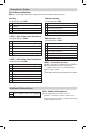
Heat Only
Set System Type to 11CONV
Rh
24VoltACPower(heatingtransformer)[note 1]
W1 HeatRelay
G FanRelay[note 3]
C 24VoltACTransformerCommon
1 HEAT / 1 COOL Single or Dual Transformer
Set System Type to 11CONV
Rh
24VoltACPower(heatingtransformer)[note 1]
Rc
24VoltACPower(coolingtransformer)[note 1]
W1 HeatRelay
Y1 CompressorRelay
G FanRelay
C 24VoltACTransformerCommon[note 2]
NOTES - Conventional Systems
[1]
Open(J3)jumperfordualtransformerinstallations.
[2]Indualtransformersystems,transformer
commonmustcomefromcoolingtransformer.
[3]Ifneededforsystem.
Provide disconnect and overload protection as required.
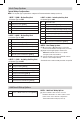
2 HEAT / 2 COOL Single or Dual transformer
Set System Type to 22CONV
Rh
24VoltACPower(heatingtransformer)[note 1]
Rc
24VoltACPower(coolingtransformer)[note 1]
W1 HeatRelayStage1
W2 HeatRelayStage2
Y1 CompressorRelayStage1
Y2 CompressorRelayStage2 [note 3]
G FanRelay
C 24VoltACTransformerCommon[note 2]
Typical Wiring Congurations
NOTE: The “System Type” option will be configured in Thermostat Installer Settings (section 4).
Conventional Systems
S1
S2
NOTES - Additional Wiring Options
[1]Theseterminalscanbeusedtoconnecta
Braeburn
®
wiredindoororoutdoorremotesensor.
IndoorremotesensormustbeconguredinThermostat
InstallerSettings(section4).
Additional Wiring Options
IndoororOutdoorRemoteSensor[note 1]
Hydronic Heat Only
Set System Type to 1HD
Rh
24VoltACPower(heatingtransformer)[note 1]
W1 ZoneValvePowerOpen
V3 ZoneValvePowerClose
G FanRelay[note 3]
C 24VoltACTransformerCommon
Hydronic Heat / 1 Cool
Set System Type to 11HD
Rh
24VoltACPower(heatingtransformer)[note 1]
Rc
24VoltACPower(coolingtransformer)[note 1]
W1 ZoneValvePowerOpen
V3 ZoneValvePowerClose
Y1 CompressorRelay
G FanRelay
C 24VoltACTransformerCommon[note 2]