
User's Manual


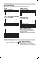


3 HEAT / 2 COOL – Including Auxiliary Heat
Set System Type to 32HP
Rh 24VoltACPower
O/B ChangeoverValve [note 1]
Y1
Compressor1Relay(1ststageheating/cooling)
Y2
Compressor2Relay(2ndstageheating/cooling)
AUX
AuxiliaryHeatRelay(3rdstageheating)
[note 2]
E EmergencyHeat[note 2]
G FanRelay
C 24VoltACTransformerCommon
L OptionalSystemFaultMonitor[note 3]
NOTES - Heat Pump Systems
[1] O(coolactive)orB(heatactive)isselectedin
theThermostatInstallerSettingsmenu(section4).
[2] Installaeldsuppliedjumperbetweenthe
AUX and Eterminalsifthereisnoseparate
emergencyheatrelayinstalled.
[3] IftheLterminalisused,the24VoltACcommon
mustbeconnected(C terminal).
Provide disconnect and overload protection as required.
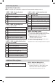
NOTES - Additional Wiring Options
[1]Theseterminalscanbeusedtoconnecta
Braeburn
®
wired
indoor or outdoor remote sensor.
Indoorremotesensormustbeconguredin
ThermostatInstallerSettings(section4).
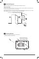
Thermostat Location
Installthethermostatapproximately5feet(1.5m)abovetheoorinanareathathasagoodamountofair
circulationandmaintainsanaverageroomtemperature.
Avoidinstallationinlocationswherethethermostatcanbeaffectedbydrafts,deadairspots,hotorcoldair
ducts,sunlight,appliances,concealedpipes,chimneysandoutsidewalls.
Install the Sub-Base:
•Removethesub-basefromthebodyofthethermostat.
•Mountthesub-baseasshownbelow:
3
UP
UP
Drill 3/16” pilot holes in your
desired location. Use supplied
anchors for drywall or plaster.
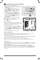
Install the Thermostat
2
NOTE: Test location by pairing your thermostat before mounting (see page 7).
5 Installer Guide