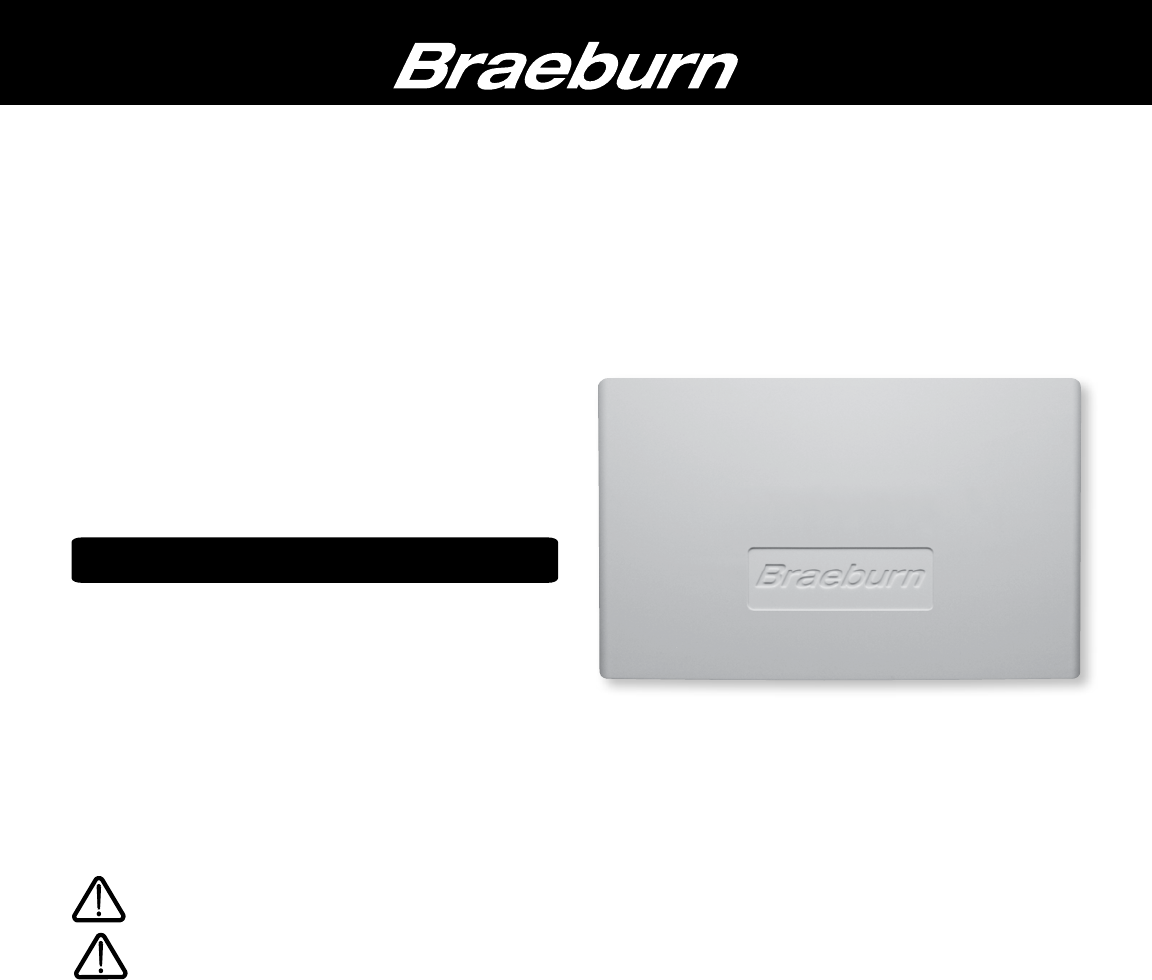
® 140424 2 Zone Expander Panel Installer Manual For Use with Braeburn Model 140404 Store this manual for future reference. Warning Caution Read all of the instructions before proceeding Voltage Hazard Can cause electrical shock or equipment damage. Always turn off power to the heating/air conditioning system prior to installing or adjusting the Zone Panel Expander. Complete the wiring for the main panel and expansion panel before applying transformer power.
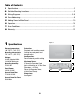
Table of Contents 1 Specifications.....................................................................................................................2 2 Suitable Mounting Locations...............................................................................................3 3 Wiring Diagrams............................................................................................................ 5-9 4 Zone Addressing....................................................................................
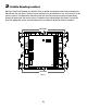
2 Suitable Mounting Locations Mount the Zone Panel Expander near the Main Panel. If desired, the expander panel can be mounted up to 500 feet from the main panel. The panel can be mounted in any orientation on a wall, stud, roof truss, or the return-air plenum. For appearance, mount the panel near the main panel for easy panel to panel wiring. Remove the panel cover and use the base as a template to drill mounting holes (see Figure 2). Attach the panel with appropriate screws.
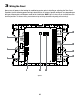
3 Wiring the Panel Always turn off power to the heating/air conditioning system prior to installing or adjusting the Zone Panel Expander. Use the following general wiring instructions for all systems. Specific wiring will vary depending on the type of thermostats and dampers used for the installation. NOTE: Up to 2 wires can be inserted into each terminal position. To release wires, press down on top of wiring terminal and gently pull out wire(s).
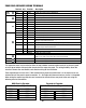
ZONE PANEL EXPANDER WIRING TERMINALS Terminal Qty.
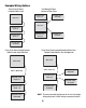
Example Wiring Options Daisy Chain All Zones Located at Main Panel Main Panel Star Wiring All Zones Located at Main Panel Expander Panel As Needed Expander Panel Zones 7-8 Main Panel Expander Panel Zones 5-6 Expander Panel Zones 7-8 Expander Panel As Needed Expander Panel Zones 5-6 Expander Panel As Needed Daisy Chain Zones Located Remote to Main Panel (Up to 500 Feet) Daisy Chain Zones Located Remote to Main Panel Remote Panels Wired in Star Configuration Main Panel Main Panel 500 Ft.
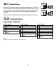
3.1 Damper Wiring PO Install the system dampers using the instructions provided by the manufacturer. Connect the dampers to the zone panel expander as shown for either a 2-wire or 3-wire damper. The sum of all dampers powered by the zone panel should not exceed 75 VA at 24 VAC. Use a slave relay if additional damper power is required. COM M PC M Zone Panel PO COM PC ALWAYS PROVIDE DISCONNECT AND OVERLOAD PROTECTION AS REQUIRED Zone Panel 3.
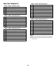
HEAT PUMP THERMOSTATS 3 HEAT / 2 COOL - With Auxiliary Heat R 24 VAC Power O/B Changeover Valve [Note 2] L Optional System Fault Monitor AX1 Auxiliary Heat Relay (3rd Stage Heating) 1 HEAT / 1 COOL - No Auxiliary Heat R O/B Y1 G C 24 VAC Power Changeover Valve [Note 2] Compressor Call (1st Stage Heating/Cooling) Fan Call 24 VAC Transformer Common [Note 1] Y1 Compressor Call (1st Stage Heating/Cooling) Y2 Compressor Call (2nd Stage Heating/Cooling) E Emergency Heat Call G Fan Call C 24 VAC T
3.3 Transformer Wiring Install the transformer using the instructions provided by the manufacturer. Size the transformer to the damper requirements. The zone panel has a built-in, selfresetting fuse. The maximum damper power per zone is 75 VA at 24 VAC. Connect the transformer to the zone panel as shown. NOTE: Additional dampers or dampers with a higher current draw will require the use of a separate slave relay.
5 Add Zones to Main Panel The 4 Zone Expandable Panel can be expanded to up to 32 zones with four zones on the main panel and 28 total expansion zones. Additional zones must have power and communication wires to be recognized and controlled by the main expandable panel. To add additional zones, complete all wiring and start the main panel test mode. Start the panel test mode to add additional zones: 1.
7 Error Conditions The Main Panel continually monitors various components of the zone system and will display a message when the following Expander Panel monitored conditions are detected. Invalid Address on Expansion Panel Displayed when an invalid address has been set on an expansion panel. This message will appear when an expander is powered up and wired to the communication terminals. To locate the expander panel with the invalid address, view the expander panel status LED.
® Limited Warranty When installed by a professional contractor, this product is backed by a 5 year limited warranty. Limitations apply. For limitations, terms and conditions, you may obtain a full copy of this warranty: · Visit us online: www.braeburnonline.com/warranty · Phone us: 866.268.5599 · Write us: Braeburn Systems LLC 2215 Cornell Avenue Montgomery, IL 60538 5 YEAR LIMITED WARRANTY Store this manual for future reference.