
Owner manual


3
Terminal Function Description
Rc* Input 24VoltACCoolingTransformer
(DualTransformerSystemsOnly)
Rh* Input PowerConnection(24VoltACHeating
TransformerorMillivoltPowerSource)
O Output ReversingValve(CoolActive)
B Output ReversingValve(HeatActive)
Y Output CompressorRelay
(appearsasY1on2200NC)
G Output FanControl
W Output ConventionalHeatRelay
C Input 24VoltACTransformerCommon
Connect Your Wires
3
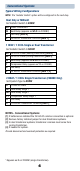
Wiring Terminations
Terminal Function Description
W1/E Output (W1)1stStageConventionalHeat
(E)EmergencyHeatRelay
W2 Output 2ndStageHeat/AuxiliaryHeat
Additional Terminations (2200NC only)
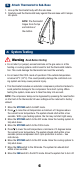
Provide Power
•For 24 Volt AC power,youmustconnectthecommonsideofthetrans-
formertotheCterminalonthethermostatsub-base.
•For primary or back-up power,insertthe2supplied“AA”typealkaline
batteriesintothebatterycompartmentlocatedonthefrontofthe
thermostat,nearthebottom.MakesuretopositionthePositive(+)and
Negative(-)sides
ofthebatteriescorrectlywiththe+/-symbolsinthe
batterycompartment.
24VAC Power
Terminal (C)
2
C
*AppearsasRon2200NC(singletransformer).