
- Product Manual RS232 Bluetooth Converter Version: 5.3


Manual for BL-521 5_3.doc © Copyright Brainboxes Limited 2004 Page 29 of 41
8. Physically connecting to your RS232 device
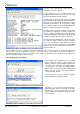
8.1. Configuring the communications parameters.
The converters do not have the ability to auto-detect the communications parameters (e.g. baud rate) so they must
be configured to match the data rate used in the application to which they are connected.
Please refer to section 4.2.3 above, for details on how to do this.
It is possible, if a little confusing, to “pair” two converters and have them physically connected to RS232 devices
which use totally different communications parameters.
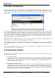
8.2. Physically connecting your device to BL-521 via the RS232 cable
BL-521 is supplied with an integral cable terminating in a 9-pin male D type connector. This DTE (Data Terminal
Equipment) configuration has been chosen to allow for easy connection to DCE (Data Communication Equipment)
RS232 devices that would normally connect directly to the RS232 port on a computer. Included is a convenient and
appropriately wired gender changer that allows the converter to behave as a DCE device (e.g. if you wish to
connect it to your computer for configuration or to Bluetooth enable the same).
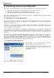
Connector Pin-Outs for the integral DTE cable (Male 9 Pin D Type) are…
As the RS232 standard allows for many different cable configurations,
your device may need an additional cable to work with the converter,
such as a “cross-over” or “null-modem” cable. Please refer to your
device’s documentation for specific details.
Pin Signal Pin Signal Pin Signal
1 N/C 4 DTR – N/C 7 RTS
2 RxD 5 Ground 8 CTS
3 TxD 6 DSR – N/C 9 N/C
When the enclosed DCE “gender changer” is connected, the (Female 9 pin D Type) Pin-Outs are…
The female connector is designed so that it can be plugged directly into
a PC’s motherboard COM port. If you are connecting it directly to a
different device you may need an additional cable, such as a “cross-
over” or “null-modem” cable. Please refer to your device’s
documentation for further details.
Pin Signal Pin Signal Pin Signal
1 N/C 4 DSR – N/C 7 CTS
2 TxD 5 Ground 8 RTS
3 RxD 6 DTR – N/C 9 N/C