
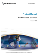
- Product Manual RS232 Bluetooth Converter Version: 5.3

Manual for BL-521 5_3.doc © Copyright Brainboxes Limited 2004 Page 5 of 41
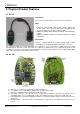
2. Physical Product Features
2.1. BL-521
Reset button
See section 6 for more details on how to use the reset button.
LED’s
a) LED1: The leftmost LED is Green. This is used to indicate the
“Power” status of the converter. When power is applied at the
specified voltage and current the LED turns ON.
b) LED2: The middle LED is Orange. It indicates transmitted data
activity.
c) LED3: The rightmost LED is also Orange. It indicates received
data activity.
Serial Cable:
BL-521 is supplied with a short (approx 20cm) length of cable
terminating in a standard 9-pin (DTE) male D type connector.
It is supplied as DTE as the main anticipated use of BL-521 is to be connected to a (DCE) device that would
normally plug into the back of a PC. If you wish to use BL-521 as a DCE device (e.g. to plug into the back of a PC
or similar) you should use the included “gender changer”. For larger volumes BL-521 can be supplied with a DCE
cable, thus removing the need for the gender changer.
2.2. BL-730
a) Antenna - The antenna is integral to the printed circuit board
b) Reset button - See “5 Resetting for details of the operation of this feature
c) LED’s - The LED behaviour is identical to the BL-521 above.
d) JST Cable connector - The BL-730 uses a 10-way JST connector. As BL-730 is designed to be an
embedded device, it is not supplied with a cable. The mating connector is JST part no. SHR-10V-S-B
e) External Antenna - Should your application require it, an external antenna can be connected to the rear of
the BL-730
f) Mounting Points - The BL-730 has 3 mounting points to allow for a secure physical connection to your
system