
User Manual


INSTALL A T ION(INSTR U C TIONS(
6503 Instructions 2-4-14.Doc Page 6 of 8
Chart B: 2013 to present Ram
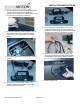
Aftermarket mirror/ display /
Aftermarket NAV
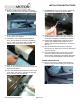
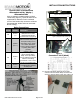
Using a commonly available Single Pull Dual
Throw Relay (Figure 3), splice the leads of the
supplied Mirror Harness to each numbered
circuit of the female relay connector as follows
(Recommended: Solder and cover with Heat
Shrink Tubing.):
Relay Connections
Circuit
Function/
Polarity
Connection
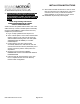
86
Reverse
(+)
Splice Relay wire to
white/tan wire in under
dash BCM white 48-pin
connector Pin 41 (Figure 4)
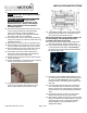
87
Ignition
(12v +)
Splice Red (Ignition) Mirror
Harness lead to Relay wire.
Then splice Relay wire to
pink/yellow wire in Cavity
19 of under dash black
I310 F Connector adjacent
to parking brake cable
grommet
(Figures 5 & 6)
85
Ground
(–)
Splice Black (Ground)
Mirror Harness lead to
Relay. Then splice Relay
wire to Chassis ground and
attach to an existing
ground bolt or use a nut to
secure to an existing stud.
30
Reverse
(+)
Splice Green (Reverse) wire
of supplied Mirror Harness
to Relay wire.
Figure 3
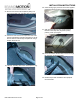
Figure 4
Figure 5
Figure 6
Connector I 310 F (black)
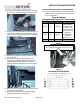
37. Plug the male Single Pull Dual Throw Relay
connector into the female Relay connector and
secure to existing vehicle wiring using a Wire Tie.
Splice Circuit 86 Relay wire to Reverse (+)
signal at white/tan wire in Pin 41.
Splice Circuit 87 Relay wire to Ignition (12v +)
signal at pink/yellow wire in Cavity 19.