
User Manual


!"#$%&&%$!'"(!"#$)*+$!'"#(
6503 Instructions 2-4-14.Doc Page 7 of 8
38. If using this kit with the factory 8.4” touch
screen, follow Steps 39 through 53 and Steps
56 through 58 below.
If using this kit with an aftermarket mirror /
display / NAV display, connect Chassis
Harness male RCA to “Camera IN” on the
aftermarket mirror / display/ NAV display.
NOTE: A RCA extension may be required.
Proceed to Step 50.
39. Use of this camera with the factory Ram 8.4” touch
screen requires activation by a Chrysler/Dodge
dealer. See below for Dealer Programming
Instructions. If possible, have the dealer “enable”
the camera option prior to installation.
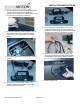
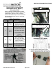
40. Use a Plastic Trim Tool to remove shifter bezel and
remove two screws from under the rubber mat using
a Phillips screwdriver.
41. Use a Plastic Trim Tool to remove cup holder bezel.
42. Remove rubber mat on top of 8.4” screen to expose
two screws and remove them using a T20 Torx bit.
43. Remove rubber mat in square cubby hole to expose
one screw and remove it using a T20 Torx bit.
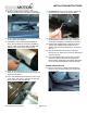
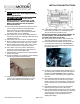
44. Use a Plastic Trim tool to remove radio bezel to
expose the 4 screws securing the radio head unit
and remove them using a 7mm socket.
45. Unplug all radio connectors from the radio head unit
and set radio aside.
46. Connect supplied 8.4” Touch Screen Jumper Harness
to RCA end of supplied Chassis Harness.
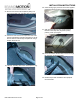
47. Locate pin position 31 on the black 52-pin radio
connector and insert Red terminal of 8.4” Touch
Screen Jumper Harness until it clicks securely.
48. Insert Black terminal of 8.4” Touch Screen Jumper
Harness into pin position 32 on the black 52-pin
radio connector until it clicks securely.
Note: If the terminals, on the jumper harness, do
not seat properly cut and splice loose wires
provided in the small zip lock bag.
49. Reconnect all radio connectors and reinstall radio
head unit and all trim removed in Steps 50-54.
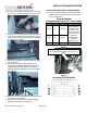
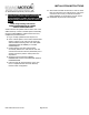
50. Route Chassis Harness behind rear cab mount and
out to the inside of the vehicle. RECOMMENDED:
Use a Wire Tie to secure Chassis Harness between
the cab and bed mount.
51. Continue to route supplied Chassis Harness next to
the existing wiring harness along the inside edge of
the frame rail. RECOMMENDED: Secure supplied
Chassis Harness to the existing wiring harness with
Wire Ties.
52. Once the Chassis Harness has been routed to the
rear of the truck bed, coil and secure any excess
length on the harness and tuck above the spare tire.
Secure with Wire Ties (recommended) or Electrical
Tape.
53. Plug Camera Harness connector into the Chassis
Harness connector at the rear of the vehicle.
54. Start vehicle and shift into Reverse in order to check
that all connections were made properly. If all of the
connections are correct you will see the camera
image displayed on your aftermarket mirror /
display/ NAV display.