
Owner's Manual


Installation Instructions Curb Alert PRO
Preparation:
1)
Identify
and
familiarize
yourself
with
all
components
of
kit
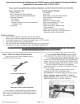
• A:
Proximity
Sensor
• B:
Buzzer
with
built-in
Power
Off-Lo-Hi
sw
it
ch
•
•
•
Installation:
C:
Main
Module
with
built-in
Program
Switch
D:
Accessory
pack
including Top
Mount
Bra
c
ket
as well as cable ties,
mount
tabs
and
Allen
wrench
NOTE:
Do
NOT
discard
box
as it will
be
used during calibration
of
system
at final steps .
2)
Find
an
appropriate
place
to
mount
all
components
•
The
Proximity
sensor
MUST
be
mounted
as close as possible to the center
of
the front
of
the vehicle
'Nith a dea!"
!i!:le
~f
~
ight
t~
the curb (it
i
~
a~
!_Q_ se!!s0r
:!!!d
so it
CANNOT
be !!!0un.ted behin.d the
license plate,
any
panel
and
or
object that
wi
ll obstruct its view).
Note:
the
sensor
must
be
placed
where
it will n
ot
be
easily struck
or
damaged
by
road
debris
or
so
low
that
it will
be
damaged
during entry
or
exit out
of
driveways.
•
The
Buzzer
must
be
accessible to the vehicle o
wner
in order to allow operation
of
the built-in
Power
switch.
The
Main
Module
must
be
mounted
in the
ca
bin area
where
it will
be
easy to
program
for
proper
operation
once
installed (the
program
switch will
NOT
be
used
by
customer
once
installation
and
proper
programming
is done
and
so
it
can
be
hidden out
of
sight).
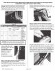
3)
Installing
hardware:
•
Clean
the
mounting
surface
where
the sensor will
be
adhered using a clean cloth and a cleaning
solution
or
alcohol. \
\Make
sure
not
to leave any residue
on
the surface (do
NOT
tighten
Allen
screw
completely as the sensor will
be
adjusted later during programming).
•
Route
the
sensor
harness through the frrewall into cabin area
making
sure to stay
away
from any
moving
parts
and
away from extreme
temper
ature engine components.
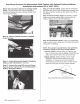
Mount
the
Buzzer
by
frrst cleaning the surface
with
either
a cleaning solution
or
alcohol.
Mount
the
Main
Module
using the supplied cable ties
making
sure
not
to obstruct
any
objects such as
the steering
column
and
or
toot
petals
unde
r
th
e steering
column
area (make sure
that
nothing will
accidentally press the
Program
switch as
th
is will de-calibrate the unit).
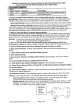
Connect
the
buzzer
as well as the
sensor
co
nn
ec
tor
to the module, leave about a
118
th
of
an
inch
of
slack.
Use
a cable tie to secure
them
to
th
e pow
er
cable (this will insure that the connections
will
not
come
lose
while
vehicle is
in
normal
opera
ti
on
).
4)
Power
connection:
•
Connect
the
BLACK
wire
of
the
power
harness to a
good
solid
ground
(it is
recommended
to trim
cable to appropriate length).
220
East Huron
St
Suite
235
Ann
Arbor,
MI
48104
www.brandmotion.com
1
Tel
734-619-1250
Fax
480-247-5999