
Owner's Manual


Dual
Mount Universal Kit Aftermarket
CMOS
Camera with
Optional
Parking Grid
lines
Installation
Instructions (Kit #
9002-7601)
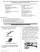
Step 3: Determine
location
of
vehicle
power and
ground.
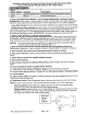
Using a
vehicle
specific service guide and/or
specific wiring diagram and a multi-meter
or
computer-
safe test light, locate
which side
of
the
vehicle
contains
Ignition and Ground wires
(Chart
A).
ChartA
•re
J\<',
f£1~&
'f'*
'lli' . . , ' , ,
I
W'
'~
~Wltlfll;:;l',
"!';'\k
"'. "
,.
'\q
Color
II
Polalitv
~~!X.
Function
,
Description
~'';:\'C,,
~
~
::
~
~
:<'t};xtl
,.',
Location
't,z:;s,'
This lead will
display
Commonly
Ignition
12
volt+
when the
found on
Red
12v
+
controlled
key
is
in the
RUN
main
power Ignition
position
harness.
A ground
bolt is
commonly
found in the
Black
(-)
Ground
Chassis
ground front kick
panel area
with other
wires
attached.
CAUTION:
Once correct wires have been identified,
turn Ignition key
OFF
and
DO
NOT
TURN
key back
ON
until
the install
has been completed (Step
13).
Step 4:
Splice
the
red
and
black
Power Harness
leads
into
the
corresponding
vehicle
wires
(Recommended:
Soldering
or
T -taps
as
optional
connection
method).
Also
recommended
is
an
eyelet
for the ground connection.
Step 5:
Insert
the
connector end
of
the
Camera
Harness through
the
hole
you
drilled.
(RECOMMENDED:
Protect
Camera
Harness from sharp
metal
edges by
applying
a small
amount
of
silicone caulk
or
a rubber grommet
to
the area
that
comes into contact
with the
metal).
7601 Instructions 9-18-12
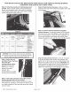
Step 6: Route
Camera
Harness.
Continue
routing
harness
to
the side
of
the vehicle
that
supplies
power and
then forward.
Step 7:
Connect Camera Harness
to
supplied
Chassis
Harness.
The
optimal location
for this junction
may occur
at
the top
of
the
liftgate
or
the inner edge
of
the trunk depending on vehicle
in which installation
is
in
(Note: most
vehicles may
already
have existing wires
passing through this area; use this route
if
at
all possible).
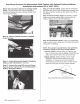
Step 8: Route
Chassis
Harness.
It
may be necessary
to
remove
sill plates, pillar
covers, seat bottoms, side
panels,
etc.
In
some cases even the
seatbelt bolts
at
the
bottom
of
the
pillars
must be removed
(CAUTION:
Any
bolts
removed
for
safety devices must
be
retightened
to
manufacturer's specified torque specifications).
Use
a
plastic
trim
removal tool
to
avoid damage
to
trim pieces.
Page
2
of
3