
Owner's Manual


Dual
Mount
Universal
Kit
Aftermarket
CMOS
Camera
with
Optional
Parking Grid lines
Installation
Instructions
(Kit
#
9002-7601)
Step
9: Secure Camera Harness
to
existing
vehicle
wiring.
This
will
minimize the chance
of
binding
or
otherwise damaging the harness (Recommended: Wire
Ties or
Electrical
Tape.)
Step
10:
Connect
Chassis
Harness
to
supplied
Power
Harness.
Step
11:
Install
aftermarket
display/
Navigation
display
as
per
instructions
(if
required).
Step
12:
Connect
the
male
RCA
from
the
Power
Harness
to
the
"Camera
IN"
on
the
aftermarket
display
I
Navigation
display.
Note:
Connection
to
female
RCA
connector
shown.
7601
Instructions
9-18-12
Step
13:
Test
the
system.
Inspect
that
all
connections
are proper and secure. Clear all loose
items removed from
the area around the
vehicle
and turn ignition key
ON
to
test system.
Step
14:
Adjust
Camera
angle
(if
necessary). Loosen
camera screw using
supplied Allen
wrench
to
aim the
camera. Tighten screw
at
desired adjustment.
Step
15:
Reassemble
vehicle.
Follow
your disassembly
steps
in
reverse order, taking care not
to
bind the harness
wiring when
reinstalling.
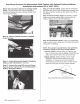
NOTE:
This
camera
has
grid
lines
or
non
grid
lines
and
mirror
image
or
non
mirror
image
options.
Grid
line
options:
Default
setting
is
to display grid
lines.
To remove the grid line display,
connect the
two
green wires near the end
of
the camera harness.
Display
options:
Default
setting
is
mirror image
display
for rearward facing camera (rear view)
installation.
To change to non mirror image for
forward facing camera
(front
view) connect the
two
white wires near the end
of
the camera harness.
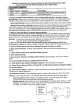
Green
and
white
wires
on
the
camera
harness.
Page
3
of
3