
Owner's Manual


Installation
Instruction
Overview Dual
Mount
Universal
Kit
Aftermarket
CMOS
Camera
with
Optional
Parking
Gridlines
{Kit#
9002-7601)
ct.;llliJ
t
•,4
=-
•I••l~
I~
I •
l
..
l{l]~~,
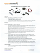
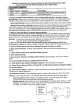
Wire
Color
Polar!ty
Function
Connection
Reel
12v
+
Ignition
Supplied
Power
Commo111y
found
on
main.Ignition
harness
···
Black
-
Ground
Good
chassis
ground
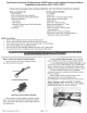
1: Select
and
Install
Camera
Bracket.
Choose
License
Plate
Bracket
or
Alternate
Camera
Mount
Bracket.
Place
camera
in
desired
position
to confirm fitment
(Note:
Some
states
prohibit
items
blocking
the
license
plate;
check
local
authorities to confirm
legal
status
for your
specific
application).
License
Plate
Bracket:
Remove
vehicle
license
plate.
Reattach
license
plate
securing
bracket
behind.
Alternate
Camera
Mount
Bracket:
.·
Remove
camera
from
License
Plate
Bracket
using
supplied
Allen
wrench.
Attach
camera
to
Alternate
camera
Mount
bracket
and
apply
supplied
self-adhesive
foam
to
mount.
Use
Template
below
to
locate
Alternate
camera
mount
on
the
vehicle:
Clean
vehicle
surface
and
affix
by
exposing
self-adhesive
foam.
RECOMMENDED:
Permanent
attachment
using
small
screws.
2: Measure, mark, and
drill
1
/4
n
hole
for
camera harness.
3: Determine location
of
vehicle
power
and
ground.
Using
a
vehicle
specific
service
guide
and/or
wiring
diagram
and
a
multi-meter
or
computer-safe
test
light,
locate
which
side
of
the
vehicle
contains
wires
into
which
you
will
need
to
tap
for
the
Power
Harness
wiring
(see
Required
Connections
above).
CAUTION:
Once
correct
wires
have
been
identified, turn Ignition
key
OFF
and
DO
NOT
TURN
key
back
ON
until
the
install
has
been
completed
(Step
13).
4:
Splice
the
red and
black
Power Harness
leads
into
the
corresponding vehicle
wires
(Recommended:
Soldering
or
T-taps
as
optional
connection
method;
eyelet
for
the
ground
connection.)
5:
Insert
connector end
of
the
Camera
Harness
through
the
hole
you
drilled.
6: Route Camera
Harness.
Continue
routing
harness
to
side
of
vehicle
that
supplies
power
and
forward.
7:
Connect Camera
Harness
to
supplied Chassis Harness.
8: Route Chassis
Harness.
9: Secure
Camera
Harness
to
existing
vehicle
wiring.
(Recommended:
Wire
Ties
or
Electrical
Tape.)
10:
Connect Chassis
Harness
to
supplied
Power Harness.
11:
Install
aftermarket
display
I
Navigation
display
as
per
instructions (if required).
12:
Connect
Power Harness
RCA
to
"Camera
INn
on
aftermarket
display/
Navigation display.
13:
Test
the
system.
14:
Adjust
Camera angle
(if
necessary).
Loosen
the
camera
screw
using
supplied
Allen
wrench
to
aim.
Tighten
screw
at
desired
adjustment.
15: Reassemble vehicle.
Follow
disassembly
steps
in
reverse
order,
taking
care
not
to
bind
harness.
NOTE:
This
camera
has
grid
lines
or
non
grid
lines
and
mirror
image
or
non
mirror
image
options:
Grid
line
options:
Default
setting
is
to
display
grid
lines.
To
remove
the
grid
line
display,
connect
the
two
green
wires
near
the
end
of the
camera
harness.
Display
options:
Default
setting
is
mirror
image
display
for
rearward
facing
camera
(rear view)
installation.
To
change
to
non
mirror
image
for forward
facing
camera
(front
view)
connect
the
two
white
wires
near
the
end
of
the
camera
harness.
7601
Instruction
Overview
9-18-12
Alternative
camera
Mount
Template
Page
1 of 1
1/lr'JJ
lf'---rulf)
Tl
~
~JlJU
3/3Z'